Largest main caliber. Super-cannons for super battleships are the largest naval guns. The main types of modern artillery shells
By the end of the 19th century, the generally accepted standard for the main caliber guns of battleships was 12 inches (305 mm) - a compromise between weight, rate of fire and armor penetration. A new round of growth in calibers began at the beginning of the new century: the introduction of electrical mechanisms made it possible to ensure a high reloading rate, the displacement of battleships increased significantly and it became much easier for them to carry huge barrels, the improvement of fire control devices led to a significant increase in the combat distance. Among the warships of the First World War, the carrier of the largest guns was supposed to be the British "light-line" cruiser Furious, which was laid down in 1915: it was supposed to be equipped with two 457-mm guns. The cannon weighed 150 tons and could send a 1507-kg projectile to 27.4 km every 2 minutes. True, in 1917, without having entered service, the cruiser was converted into an aircraft carrier. The bow tower was replaced with a 49 m long take-off deck. The dismantled gun was mounted on a General Wolf monitor and was used to shell the German coastal structures. Of course, the installation of such a colossus on a ship with a displacement of 6100 tons led to the fact that the firing sector was only 10 ° to the starboard side.
Japanese naval doctrine required that each warship be stronger than the corresponding ship of a potential enemy, so the Japanese decided to build battleships with the "over" prefix. The construction of the ships Yamato and Musashi, begun at the end of 1937, required the concentration of all the efforts of the country's industry. These battleships became the largest and strongest artillery ships in the world. Their huge 460-mm cannons weighing 158 tons were 23.7 m long and fired shells weighing from 1330 to 1630 kg (depending on the type). At an elevation angle of 45 °, these products with a length of 193 cm flew 42 km, with a rate of fire of 1 shot in 1.5 minutes. The battleships' all-or-nothing reservations included 410-mm armor belt and the thickest deck in history - 230 mm, and the frontal plate of the turret was 650 mm thick - the thickest armor ever installed on battleship! They were powerful combat vehicles, extremely dangerous in battle for any battleship. However, the concentration of armor within the citadel resulted in nearly two-thirds of the ship's length being nearly exposed. The military fate of the super battleships developed in such a way that they never had to measure their strength with their own kind. Musashi was sunk by American aircraft in the Sibuyan Sea on October 22, 1944, becoming one of the first casualties of the Japanese fleet in the battle for the Philippines. On April 5, 1945, the same fate befell the Yamato, heading for Okinawa to repel the American landing.
Around the same time, the Americans managed to create a very successful cannon for their last battleships. Their 406-mm cannon fired a 1055-kilogram projectile at a speed of 820 m / s. The firing range could theoretically reach 50.5 km.
Guns of similar power were designed for the battleship Sovetsky Soyuz, laid down in 1939 in Nikolaev. The sixteen-inch of this 65,000-ton giant threw its 1,000-kilogram shells 45 km. When in the fall of 1941 german troops approached Leningrad, one of the first, from a distance of 45.6 km, it was met by shells from the Naval Research Test Site - the prototype of the main caliber guns of the battleship that had not yet been built.
In conclusion, we will mention the laid down, but not even launched, German battleship N-44. It was supposed to have a displacement of 139,277 tons, a speed of 30 knots and carry eight 508-mm guns.
On the closed territory of the Rzhevsky test site there is a weapon that could rightfully be called the "Main caliber of the Soviet Union". With equal success, it can claim the title of "Tsar Cannon". Indeed, its caliber is no less than 406 mm. Created on the eve of World War II gun mount was intended to arm the world's largest battleships Sovetsky Soyuz, Sovetskaya Belorussia and Sovetskaya Rossiya. These plans were not destined to come true, but the cannons themselves did a good job during the defense of Leningrad and by this alone earned the right to take a worthy place in the museum. But so far, a unique Russian monument does not even have the status of a museum exhibit ...
Anyone who has been to the Moscow Kremlin, of course, saw there the famous "Tsar Cannon", cast by the Russian gunsmith Andrei Chokhov in 1586. But few people know that its Soviet counterpart exists. This is the largest-caliber artillery gun of the Soviet Union, which passed field tests on the eve of the war, and during the Great Patriotic War defended besieged Leningrad from the enemy.
In the early 1920s, the naval and coastal artillery of the Soviet Navy lagged significantly behind the corresponding artillery of the leading capitalist states. At that time, a whole galaxy of talented designers of naval artillery systems and organizers of their serial production worked in the USSR: I.I. Ivanov, M. Ya. Krupchatnikov, B.S. Korobov, D.E. Bril, A.A. Florensky and others.

Designers Ivanov I.I., Krupchatnikov M.Ya., Grabin V.G. (from left to right)
The greatest success of Soviet designers and artillery factories was the creation of a unique and complex 406-mm artillery system - the prototype of the main caliber guns of the new battleships.
In accordance with the new shipbuilding program of the USSR, new battleships were laid on the stocks of shipyards: in 1938 - "Soviet Union" and "Soviet Ukraine", in 1939 - "Soviet Belarus" and in 1940 - "Soviet Russia". The total displacement of each of the battleships, which embodied the traditions of domestic shipbuilding and the latest achievements of science and technology, was 65,150 tons. The power plant was supposed to provide a speed of 29 knots (53.4 km / h). The main armament of the battleships - nine 406-mm guns - was housed in three armored towers, two of which were in the bow. Such an arrangement of the main caliber made it possible to direct and concentrate the fire of 16-inches in the best way, firing thousand-kilogram shells at a distance of 45 km. The artillery armament of the new battleships also included twelve new 152-mm guns, eight 100-mm universal guns, and thirty-two 37-mm anti-aircraft guns provided air defense for each ship. Artillery guidance was carried out using the latest rangefinders, automatic fire control devices and four spotter seaplanes, for which a catapult was envisaged to launch.

The projected 406-mm turret installation was a unique artillery system, for which all elements - from the gun itself to ammunition - were developed for the first time.
The very experimental gun mount MK-1 was manufactured in less than a year.
By order of the People's Commissar of the Navy, Admiral N.G. Kuznetsov No. 0350 dated June 9, 1940 for the production of field tests of the 406-mm B-37 gun, the swinging part of the MK-1 for the B-37 gun, the MP-10 polygon machine and ammunition for the gun mount (shells, charges, powder and fuses) was a commission was appointed under the chairmanship of Rear Admiral I.I. Grena. The test program, developed by ANIMI (Artillery Scientific Research Marine Institute), was approved by the head of the AU of the Navy, Lieutenant General of the Coastal Service I.S. Mushnov. Military engineer of the 2nd rank S.M. was appointed the head of the tests. Reidman.

Engineer-Captain 2nd Rank S.M. Reidman. 1943 g.
Field tests began at the NIMAP (Scientific Research Naval Artillery Range) on July 6, 1940. The total volume of tests was determined at 173 shots with an expected barrel survivability of 150 shots.
The ballistic characteristics of the gun were as follows: the initial flight speed of the projectile with its weight of 1 105 kg - 830 m / s, the muzzle energy - 38 800 tons, the maximum pressure of the powder gases in the barrel bore - 3 200 kg / cm2, the maximum range of the projectile - 45.5 km. The weight of the swinging part is 198 tons, the ratio of muzzle energy to the weight of the swinging part is 196.5 tons. The mass of the barrel with the breech and the B-37 bolt was 140 tons, and the rate of fire of the gun was 2.6 rounds per minute.
During this period, a lot of work was done at the naval artillery range to prepare the measuring base, which by 1940 had reached a very high level and made it possible to widely use instrumental control methods in testing practice, including oscillography of dynamic processes.
The preparation and conduct of the tests were difficult and stressful, especially in terms of the preparation of ammunition (projectile weight - 1,105 kg, charge - 319 kg), it took a lot of time to dig them out of the ground after the shot, assemble and deliver them to the laboratory for inspection and measurements. Many of the experiments in the testing process were innovative. So, when firing at a distance of 25 km, to find out the reasons for the increased dispersion of shells, it was necessary to build ballistic frames with a height of 40 meters. At that time, the initial flight speed of the projectiles was determined only by chronographs, therefore, after each shot on these target frames, it was necessary to change the wire wound damaged by the charge, which also presented great difficulties. Each shot from the B-37 gun was of high importance, so the tests were built very thoughtfully in the interests of the entire complex of tasks. The results of each shooting were considered in the subcommittees on the affiliation of the issues and were very often discussed at the general meeting of the commission.
On October 2, 1940, field tests of the B-37 gun, the swinging part of the MK-1, the MP-10 machine tool and ammunition were completed.
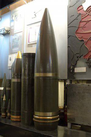
406 mm (16-inch) shell for the B-37 cannon. Central Naval Museum
In the conclusions of the commission's report, it was noted: "The tests carried out on the 406/50-mm B-37 gun, the swinging part of the MK-1 and the MP-10 polygon machine gave quite satisfactory results." This is how succinctly was noted the many months of hard work of design engineers and test artillerymen.
The swinging part of the MK-1 with the B-37 gun was recommended by the commission for serial production with some design changes.
Admiral of the Fleet of the Soviet Union N.G. Kuznetsov in his memoirs "On the Eve" recalls: "... In August I went to the Baltic ... The head of the naval test site, Rear Admiral II Gren, asked me to visit the test of a new, twelve-inch gun." The best gun in the world, "he said. And As life has shown, I did not exaggerate. They also showed me a sixteen-inch cannon for future battleships. This weapon - a vivid proof of our economic capabilities and the talent of Soviet designers - also turned out to be excellent ... "

Rear Admiral I.I. Gren. 1942 g.
October 19, 1940, due to an exacerbation international environment, the Soviet government adopted a decree on the concentration of efforts on the construction of small and medium warships and on the completion of laid down large ships with a high degree of readiness. The battleship "Sovetsky Soyuz" was not among the latter, so the serial production of 406-mm guns was not deployed. After the end of the range tests, the B-37 gun continued to remain at the NIMAP in Leningrad.
On June 22, 1941, the Great Patriotic War began. In the first weeks, Hitler's troops managed to penetrate the territory of the Soviet Union. In mid-August 1941, fierce battles began on the near approaches to Leningrad. As a result of the enemy's rapid advance, a threatening situation developed. Mortal danger looms over the city. The Red Army troops courageously repulsed attacks from superior enemy forces in all directions.
The Red Banner Baltic Fleet, concentrated in Leningrad and Kronstadt at the end of August 1941, provided significant assistance to the Leningrad Front with its powerful long-range naval and coastal artillery, which covered the city with a reliable fire shield throughout the blockade.
Immediately after the start of the war, NIMAP took an active part in resolving issues related to the preparation of Leningrad for defense. In the shortest possible time, a skillful, quick and purposeful restructuring of its work was carried out in the interests of the city's defense. Due to their heavy weight, the gun mounts of the naval range could not be evacuated, and they began to prepare them for the battle for Leningrad.
In July-August 1941, at the naval artillery range, all available artillery weapons were brought into battle, an artillery division and a local air defense team were formed and prepared for combat operations.
During the preparation of NIMAP for the defense of Leningrad, the barrel was changed and the 406-mm gun (B-37) was armored, all gun mounts were prepared for circular fire, aiming points with a light guide for night firing were installed, four command posts of artillery batteries and two armored artillery cellars were installed near firing positions.

Military technician 1st rank Kukharchuk, commander of battery No. 1 NIMAP, which included a 406-mm gun. 1941 g.
The entire artillery of the naval range consisted of fourteen guns: one 406 mm, one 356 mm, two 305 mm, five 180 mm, one 152 mm and four 130 mm. The 406 mm gun was included in battery No. 1, which, in addition to it, also included one 356 mm and two 305 mm guns. These were the main guns, the most powerful and long-range ones. The commander of the battery was appointed 2nd rank military technician Alexander Petrovich Kukharchuk.
At the end of August 1941, the NIMAP artillery was ready to start performing combat missions, and on the eve of this the following message was published in the Leningradskaya Pravda newspaper: . The military commandant of the city of Leningrad, Colonel Denisov. "
NIMAP fired its first combat shots on August 29, 1941 at the concentration of enemy troops in the area of the Krasny Bor state farm in the Kolpino direction from the B-37, the most powerful and long-range weapon of the USSR Navy. And already at the beginning of September, a column of enemy tanks was moving in the same direction in order to break through to Leningrad, and again the powerful explosions of 406-mm shells lying in the head and tail of the column caused confusion among the enemy and forced him to stop. The surviving tanks turned back. People's militia fighters from the Izhora battalion, who defended Kolpino, always remembered with great gratitude the artillerymen of the naval range, who, with their fire, helped them in 1941 to hold the defensive lines on the outskirts of Leningrad.
From August 29 to December 31, 1941, the NIMAP artillery opened fire 173 times, destroying large concentrations of enemy personnel and equipment and suppressing its batteries. During this period, the 406-mm gun fired 81 shells (17 high-explosive and 64 armor-piercing) at the enemy.
In 1942, the naval artillery range carried out 9 live firings. On February 10, the B-37 gun supported the offensive operation of the 55th Army in the area of the settlements of Krasny Bor, Yam-Izhora and Sablino with its fire. Three shells were expended. It is known about the results of this operation that: "... in the area where the 55th Army held the defense, the artillerymen distinguished themselves. In one day they destroyed 18 guns and 27 machine guns, destroyed 19 bunkers and dugouts." The 406-mm gun of the naval artillery range also contributed to these enemy losses.

Command and engineering staff of the Scientific Testing Naval Artillery Range (NIMAP). 1942 g.
This is how an eyewitness of those events, a participant in the defense of Leningrad, Nikolai Kislitsyn, describes his impressions of the combat use of the B-37: “I recall how, among the habitually sounding explosions of shells and shots of our artillery, a dull powerful sound was occasionally heard somewhere shaking the glass. I was perplexed until I met one artilleryman.It turned out that in the pre-war period the design and construction of the latest high-class surface ships were launched. The gun was successfully tested. In connection with the outbreak of the war, the tests were stopped. When Leningrad was in the blockade, this powerful weapon was used to destroy important military targets deep in the enemy's location. The stock of shells was small, and when it was used up, the gunners became and dig up shells deeply buried in the ground during tests and bring them into a combat state. Enemy aircraft searched in vain for the firing position of this giant, skillful camouflage helped him stay undetected ... "
On December 8, 1942, the Headquarters of the Supreme High Command of the Red Army issued a directive to conduct an offensive operation to break the blockade of Leningrad.
The operation began on January 12, 1943 at 9:30 am. For 2 hours 20 minutes an artillery hurricane raged on enemy positions - this was hitting 4,500 guns and rocket launchers from two Soviet fronts and the Red Banner Baltic Fleet: 11 artillery batteries of stationary coastal artillery, 16 batteries of railway artillery, artillery of the leader "Leningrad", 4 destroyers and 3 gunboats. The artillery of the Red Banner Baltic Fleet also included a 406-mm gun of the naval artillery range.
On January 12, for 3 hours 10 minutes, it conducted methodical fire at the enemy's resistance nodes in the area of the 8th hydroelectric power station, 22 high-explosive shells were used up.
On February 13, it also conducted artillery fire at the defensive lines, fire weapons and manpower of the enemy in the area of the 8th hydroelectric power station and the 2nd Workers' settlement, 16 shells were used up (12 high-explosive and 4 armor-piercing).

The ruins of the 6th hydroelectric power station after shelling with a 406-mm gun during the operation to break the blockade of Leningrad. January 1943
At the end of 1943, Leningrad remained on the front line of fire. If enemy aircraft no longer had the opportunity to bomb the city either in November or in December, then shelling from large-caliber guns continued. Artillery shelling kept Leningrad in constant tension, it was necessary to rid the city of them. Considerations of the strategic plan demanded a complete lifting of the blockade of Leningrad and the expulsion of the German fascist invaders from the Leningrad region.
The headquarters of the Supreme High Command, planning military actions to liberate the territory of the Soviet Union, decided to start 1944 with an offensive operation near Leningrad and Novgorod (First Stalinist strike).
On January 14, 1944, the start of the operation was scheduled for the complete liberation of Leningrad from the enemy blockade.
On the morning of January 14, for 65 minutes, enemy positions were fired upon by the artillery of the Leningrad Front and the Red Banner Baltic Fleet, 100 thousand shells and mines fell on the enemy's battle formations.
On January 15, the troops of the Leningrad Front dealt a powerful blow to the enemy from the Pulkovo Heights. 200 guns and mortars destroyed enemy fortifications for 100 minutes, literally plowing trenches and communication trenches, bunkers and bunkers. More than 200 guns of the Red Banner Baltic Fleet's naval and coastal artillery struck at the positions of large-caliber artillery, resistance centers and strongholds of the enemy.

Enemy bunker destroyed by 406-mm gun fire. Red Village. January 1944
In the offensive operation, the Leningrad Front was supported by the Red Banner Baltic Fleet artillery consisting of 215 guns with caliber from 100 to 406 mm. The attraction of large-caliber coastal (stationary and railway) and naval artillery ensured the defeat of targets located at a significant distance from the enemy's forward defense.
On January 15, a 406-mm gun fired at planned targets in the area of Pushkin, 30 shells were expended.
On January 20, it fired at targets in the area of the village of Koporskaya and railway. d. station Antropshino, three shells were used up.
From 15 to 20 January 1944, during the offensive operation of the Leningrad Front for the complete liberation of Leningrad from the enemy blockade, the B-37 gun fired 33 shells (28 high-explosive and 5 armor-piercing).
In the course of this operation, target number 23 (height 112.0) was destroyed - the enemy's resistance center on the approaches to Pushkin from the north.
On the destruction of this target with a 406-mm gun of the naval artillery range, the former commander of the Red Banner Baltic Fleet, Admiral V.F. Tributs recalled this: “I knew about this so-called target number 23 before. But nevertheless I checked my assumptions by phone, called the commander of the fourth [artillery] group, Engineer-Captain 1st Rank ID Snitko. He confirmed my information, and I instructed him to fundamentally tackle the harmful “nut.” The 406 mm gun managed to crack it. At the height of 112, an explosion soon exploded and a huge conflagration broke out.
The artillery of the Red Banner Baltic Fleet fulfilled the tasks assigned to it to ensure the offensive of the troops of the Leningrad Front and the liberation of Leningrad from the enemy blockade. For 14 days of the offensive operation, she conducted 1,005 firing, firing 23,600 shells of various calibers from 100 mm to 406 mm at the enemy.
After the defeat of the Nazi troops in the southwestern direction, Leningrad was still threatened from the northwest, from Finland, whose army had been on the defensive on the Karelian Isthmus for about three years.
In the Vyborg offensive operation from the Red Banner Baltic Fleet took part 49 ships (130-305 mm); 125 coastal (100–406 mm). In accordance with the order of the commander of the KBF artillery No. 001 / OP dated June 2, 1944, two long-range guns of the naval range, 406 mm and 356 mm, entered the third artillery group.
During the first four days of the offensive, the Red Banner Baltic Fleet's artillery fired 582 and consumed more than 11,000 rounds of caliber from 100 mm to 406 mm.
On June 9, the B-37 gun fired at planned targets, while 20 shells were used up, and on June 10, it also fired at one unplanned target, and 10 shells were used up. All shells were high-explosive.
Based on the results of the inspection of the destruction of targets near the Beloostrov railway station, the following results were obtained:
- fire on the target G-208 - the command height, which was part of the general system of the enemy's resistance unit. The fire was led by a 406-mm gun. Were destroyed: a machine-gun point along with the crew, two machine-gun nests, an armored observation tower. Trenches and a section of the road were also destroyed, forcing the enemy to abandon four 76-mm guns. Many corpses of enemy officers and soldiers were left on the road;
- fire on target G-181 - command height in the village of Kameshki. The fire was led by a 406-mm gun. A direct hit from a shell destroyed a crossroads from three directions, which prevented the enemy from taking out anti-tank and anti-aircraft batteries. In the area where the positions of 152-mm and 210-mm enemy artillery batteries were located, there were craters from being hit by 406-mm shells.
As a result of the Vyborg offensive operation, a large group of Finnish troops was defeated and the northern part of the Leningrad region was liberated, after which the battle for Leningrad was finally completed.
For the B-37 gun, these were the last combat shooting.
Over the entire period of the defense of Leningrad, 185 shots were fired from a 406-mm gun, while 109 high-explosive and 76 armor-piercing shells were fired.

A memorial plate commemorating the military merits of the 406-mm gun of the Red Banner NIMAP. Central Naval Museum
After the end of the Great Patriotic War, by decision of the command of the Navy, a memorial plate was installed on the B-37, which is currently kept in the Central Naval Museum in St. Petersburg. It embossed the following: "406-mm gun mount of the Navy of the USSR. This gun of the Red Banner NIMAP from August 29, 1941 to June 10, 1944 took an active part in the defense of Leningrad and the defeat of the enemy. With well-aimed fire, it destroyed powerful strongholds and nodes resistance, destroyed military equipment and manpower of the enemy, supported the actions of units of the Red Army of the Leningrad Front and the Red Banner Baltic Fleet on the Nevsky, Kolpinsky, Uritsko-Pushkinsky, Krasnoselsky and Karelian directions. "
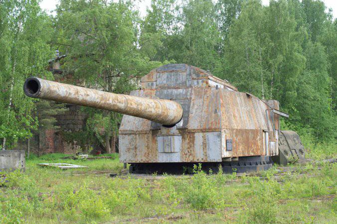
406-mm gun mount at the Rzhev training ground. 2008 r.
To preserve this for posterity unique weapon, it is necessary to create at the Rzhevsky training ground a Museum of naval weapons and equipment, which will house exhibits that, due to their weight and size characteristics, do not fit within the walls of other military history museums. And such exhibits, in addition to the B-37, are already available. For example, standing next to a 406-mm gun mount a 305-mm coastal gun of 1915, which also defended Leningrad during the Great Patriotic War, and the barrel on it, by the way, was inherited from the battleship "Empress Maria".
Museums of military equipment and weapons - tank, aviation, automobile, etc. - the interest in which is constantly growing, already exist in other regions. So maybe it's time to organize a similar museum in St. Petersburg - a museum of naval weapons and equipment? It will also be possible to present the experimental and test work of the naval training grounds. And it doesn't matter that this museum will not be located in the historical center. After all, there are museums far from the city center, visited with no less interest. It would be interesting to know the opinion of the Minister of Defense of the Russian Federation and the Governor of St. Petersburg on this issue, because the decision to create a new state museum at the Rzhev test site must be taken today.
406-mm ship gun B-37
Classification
Production history
Operation history
Tool characteristics
Projectile characteristics
406 mm naval gun B-37- a naval gun in three-gun turret mounts, which received the code MK-1 (Naval Ship No. 1), was supposed to be installed on battleships of the "Soviet Union" type. In connection with the termination of the construction of battleships of the "Soviet Union" type in July 1941, work on the creation of the B-37 gun and the MK-1 turret were stopped.
Prehistory of the B-37 gun
By 1917, the production of naval guns with a caliber of up to 356 mm was mastered. From 1912 to 1918, an experimental 406-mm gun for future battleships was being created at the steel plant. Also, the plant made sketches of three- and four-gun turrets. Work on the first Russian 406-mm naval gun was stopped, when the gun itself was already 50% ready.
In the 1920s, naval artillery in the USSR fell into complete decline. But in spite of everything, the constant modernization of the old battleships of the "Sevastopol" type helped to preserve and train new personnel. Since 1936, the development of technical specifications for all Soviet naval artillery installations, as well as the consideration of projects, was carried out by the Artillery Research Marine Institute (abbreviated as ANIMI), which was led by the famous artilleryman and Vice Admiral I.I. Gren.
Design
The choice of the 406-mm main battery gun for battleships of the "Soviet Union" type was caused by the fact that such guns were installed on powerful battleships of foreign fleets. Attempts to increase the caliber of the main battery during the First World War ended in failure and were not followed up. And the Soviet naval leadership did not have information about increasing the caliber for foreign battleships more than 406 mm in 1936. In Russia, and later in the USSR, 356-mm guns were the best mastered by our industry. And the research of the Naval Academy revealed that battleships with a displacement of 50,000 tons or more, possessing 356-mm guns, will be less effective than with 406-mm guns or 457-mm guns. It was decided to abandon 457-mm guns due to the technological difficulties in mastering such guns.
Initially, the performance characteristics of the B-37 gun were as follows: projectile weight - 1105 kg, muzzle velocity - 870 m / s, firing range - 49.8 km, vertical guidance angle - 45 °, barrel bore pressure - 3200 kg / cm². An armor-piercing projectile, at the request of a tactical and technical assignment, was supposed to penetrate the side armor 406 mm thick at a distance of 13.6 km. The designers carried out calculations of the barrel cutting in 25 and 30 calibers of constant steepness. Also, two barrel options were developed: bonded and lined. The performance characteristics for a three-gun turret installation were developed by ANIMI employees in the summer of 1936 and were repeatedly corrected.
The design and development of the B-37 gun was carried out by the Bolshevik plant in 1937-1939. The swinging part of the B-37 cannon was developed by Professor Evgeny Georgievich Rudyaka, he also led the actual leadership on the creation of the B-37 gun. The gun barrel itself was developed by M.Ya. Krupchatnikov, who is rightfully called the founder, and most importantly, a practitioner of the theory of designing large-caliber artillery barrels. The breech bolt and the balancing mechanism were developed by G. Volosatov. The cannon liner was designed at NII-13, and a cradle with a recoil mechanism was developed at the design bureau of the Leningrad Metal Plant, the work supervisor was A. Tolochkov. The design and development of the drawings of the projectiles were carried out by the Leningrad branch of NII-24, and the fuses were developed at TsKB-22, gunpowder was created at NII-6 NKB. The final technical design of the B-37 gun was created in September 1937 and approved by the KO under the Council of People's Commissars of the USSR in 1938.
The technical design of the MK-1 tower installation with the B-37 swinging parts was completed in April 1937. The tower itself and the artillery cellars were designed by the Stalin Leningrad Metal Plant, under the leadership of D.E. Bril. According to the project, the tower was equipped with 46 electric motors with a capacity of 1132 hp. The design sketch for the MK-1 tower installation was completed in May 1937. The MK-1 drawings were ready by 1938. According to the recollections of Lieutenant General I.S. Mushnov, one set of drawings included 30 thousand Whatman papers, and, if laid out in the form of a carpet, would stretch for 200 km.
On April 11, 1938, the Order Execution Council considered the issue "On the state of design of 16-inch turret installations for battleships" A "". The commission chaired by M. M. Kaganovich, which included P. A. Smirnov, A. D. Bruskin, I. S. Isakov, I. F. Tevosyan, B. L. Vannikov and S. B. Volynsky, was instructed to “ to develop and submit to the Order Execution Council on April 20, 1938, measures to accelerate experimental work and prepare for the manufacture of 16-inch guns and turret installations at the Bolshevik and Novokramatorsky factories. " V. M. Molotov, A. A. Zhdanov, M. M. Kaganovich, A. D. Bruskin, P. A. Smirnov, I. F. Tevosyan were present at the meeting of the Order Execution Council on April 21-22. Akulin, Egorov, Vannikov, Ustinov, Shipulin, Ivanov, Lasin Tylochkin, Goremykin, Ryabikov; The meeting discussed the draft resolution of the NKOP "On measures to accelerate the detailed design of 406-mm (16-in.) guns and 3 gun turrets" and decided "to submit this draft for approval by the Defense Committee under the Council of People's Commissars of the USSR." In one of the reports of the People's Commissar of the Navy P.A. Smirnov, the reasons for the slowdown in detailed design were noted: “The technical project of the 406-mm gun by the Bolshevik plant has not been completed, due to the incomplete experimental work on the automatic firing device and the balancing mechanism of the lock, which may delay the production a prototype gun at the Barricades plant; experimental work at the Leningrad Metal Plant (named after IV Stalin) on recoil devices and Jenny's clutch is also delayed.
When designing the B-37 gun, we used the developments on the developed projects of artillery installations of caliber 305 and 356 mm, as well as data obtained during testing of an experimental bolt and shooting at the NIAP of an experienced liner in a 356/52-mm cannon, re-barreled in a 305-mm. With the beginning of the Great Patriotic War, all work on the further development of the B-37 cannon design and the creation of the MK-1 tower was discontinued.
Manufacturing and testing
Production
The very production of the artillery of the Main Committee went with difficulties due to the lack of experience, which was lost in the heat of the revolution and civil war. Also, for the production of these tools, it was required not only to update production facilities, but also to create new production facilities that would ensure the use of high-alloy steels and high-quality castings. Plants for the production of 406-mm artillery pieces and tower installations for them were identified by the beginning of 1937. And the first B-37 gun was assembled by December 1937 at the Barrikady plant (with the participation of the Leningrad metal plant and plant No. 232 NKOP Bolshevik). A cradle with a rolling mechanism for the first tool was manufactured by the Novokramatorsk Machine-Building Plant. A total of 12 guns were made (including 11 with lined barrels) and five swinging parts for them. A batch of 406-mm shells was also fired to the gun.To create the barrel of the gun, an absolute ingot of high-quality steel with a mass of more than 140 tons was required without foreign inclusions, shells, etc. For this casting of the barrel, the flow of liquid steel was carried out immediately from two open-hearth furnaces with a volume of 100 and 50 tons. And the ingot itself was forged on powerful presses, and then thermally processed in oil baths, and on special machines it was mechanically processed to drawing dimensions, deep drilling to the entire depth of the barrel, fine boring, grinding and cutting of channels. The production of one 16m long trunk often took more than a year with continuous processing. It was planned that every year, starting from January 1, 1942, 24 B-37 guns will be supplied for the needs of the Navy.
The manufacture of a barrel with a bolt and a breech was entrusted to the Barrikady plant, cradles with swinging part mechanisms - to the Novokramatorsk Machine-Building Plant. Armor-piercing and high-explosive shells were ordered to be manufactured by the Bolshevik plant, and high-explosive practical - by the Krasny Profintern plant. The fuses were manufactured at TsKB-22 NKB.
The production of tower installations was to be carried out at the Leningrad Metal Plant (No. 371 NKOP), whose contractors were the Kirov and Izhora plants, the Bolshevik, Elektropribor, GOMZ, LOMZ, SSB factories, as well as at the shipyards No. 198 (in Nikolaev) and No. 402 in Molotovsk (present-day Severodvinsk).
The manufacture and assembly of artillery towers traditionally took place at special factory stands - "pits". There they were mounted, then disassembled, transported to the installation site, where the final assembly, installation on the ship, debugging and acceptance tests took place. The tower armor was finally installed directly on the ship. The erection of the main caliber towers was to be carried out with the help of heavy-duty floating cranes.
As a result, due to the lag in the construction and equipment of tower shops at all factories and delays in the supply of steel casting, armor and electrical equipment, the planned readiness dates for all MK-1 towers were postponed. Before the beginning of the Great Patriotic War, the construction of the tower shop at plant No. 402 had not started, and the metal structures manufactured by the Verkhne-Salda plant for this shop were used for other needs with the permission of the KO. None of the MK-1 tower installations were ever fully manufactured.
Testing
From July to October 1940, at the test site near Leningrad under the government commission with I.I. Gren, experimental tests of the B-37 gun with a fastened barrel were carried out. The head of the tests was the senior engineer of the test department of NIMAP, military engineer of the 2nd rank Semyon Markovich Reidman. The gun was fired from the MP-10 single-gun mount, designed under the leadership of M.A. Ponomarev. The MP-10 gun mount itself was installed on a reinforced concrete base weighing 720 tons, this base withstand recoil when fired. Instead of a rigid drum, there was a cast steel ring weighing 60 tons and a diameter of 8 m. Also, the MP-10 gun mount was on 96 balls with a diameter of 203 mm, located on a ball chase with a diameter of 7460 mm. The length of the machine tool is 13.2 m, its height from the plane of the ball shoulder is 5.8 m. The loading with shells and semi-charges was carried out from the loading table, from there it was transferred to the loading tray, which was located along the axis of the channel. The projectiles were sent with a standard chain breaker.During the test itself, 173 shots were fired from the gun, while 17 shots were reinforced charges. For a projectile weighing 1108 kg, a charge weighing 310.4 kg was selected from gunpowder brand "406/50", the muzzle velocity of the projectile was 870 m / s, the pressure in the barrel bore when fired reached 3200 kg / cm². For firing at a lower initial speed (830 m / s), a charge weighing 299.5 kg was selected from gunpowder brand "356/52 1 / 39K". The fastened barrel withstood all 173 shots.
During the test, they had to resort to unconventional solutions. So, for example, to find out the reasons for the increased dispersion of shells when firing at 25 km, it was necessary to build a special ballistic target frame with a height of 40 m. After the next shot, the wire mesh damaged by the projectile was changed on the target frame. The commission noted an increased dispersion of projectiles in range due to poor-quality gunpowder and leading projectile belts and unsatisfactory durability of armor-piercing projectiles. Government commission also recommended to accept a lined barrel for subsequent manufacture, and recommended to issue an assignment for work to increase the speed to 870 m / s, which was allowed by the design of the gun.
In general, the test results were assessed as satisfactory, even successful, the swinging part of the MK-1 with the B-37 gun was recommended by the commission for serial production with the introduction of some design changes. Upon completion of the tests, work on bringing the gun to the tactical and technical assignment was continued. The second gun with a lined barrel was manufactured in 1940 and arrived at NIMAP for testing at the end of the same year.
Description and characteristics of the B-37 gun
The first experimental barrel of the B-37 gun consisted of the following parts - an inner tube, four fastened cylinders, a casing and a breech. Also for the first time in the history of Russian artillery, the fastening of the breech to the barrel was carried out not on the thread, but with studs and a thrust ring. The internal structure of the lined barrel, with which the gun went into mass production, was similar to the fastened barrel. Replacement of the liner at the lined trunk could be carried out in the conditions of a ship standing at the quay wall. The barrel bolt was a two-stroke piston with a three-stage thread, opened upward and had a pneumatic balancing mechanism. The shutter drives operated from an electric motor, and could also be operated manually for opening and closing. The drive motor was attached to the bracket with right side cradle covers. The weight of the swinging part of the gun was 197.7 tons. The firing device operated on a galvanic shock principle. The means of ignition of the charge were a GTK-2 galvanic tube and a UT-36 shock tube. The ammunition was sent to the gun using a chain-type punch.
Characteristics of the B-37 gun
| Specifications | The values |
|---|---|
| Caliber, mm | 406,4 |
| Barrel type | lined (for tool No. 1 - fastened with cylinders) |
| Barrel length, calibers | 50 |
| Barrel length, mm | 20720 |
| Barrel bore length, mm | 19857 |
| Length of the threaded part, mm | 16794 |
| Chamber volume, dm³ | 441,2 |
| Shutter type | piston two-stroke |
| Shutter actuators | 3 electric motors |
| Shutter weight, kg | 2470 |
| Barrel weight with shutter, kg | 136690 |
| Maximum range shooting, m | 45670 |
| Rate of fire, rounds per minute | 2-2,6 |
Gun mount
Tower structure
Tower installation MK-1, Frontal wall armor reached 495 mm, side walls - 230 mm, back wall- 410 mm, barbette - 425 mm, roof - 230 mm, shelf - 180 mm. In addition, the fighting compartment was divided in a gun-way by armored traverses 60 mm thick. The total mass of the armor of one tower installation was 820 tons. The total weight of the MK-1 tower was 2364 tons, the weight of the rotating part of the tower reached 2087 tons. The rotating part of the tower rested on a ball strap 11.5 m in diameter with 150 steel balls 206.2 mm in diameter. When fired, horizontal loads had to be perceived and transferred to the hull structures.The loading of the turret guns was carried out at a constant loading angle of 6 °. Each turret gun had an individual cradle. The recoil device system consisted of two pneumatic knurls, four spindle-type rollback and rollback brakes, and four additional rollback buffers symmetrically to the tool axis. The retractable part of the gun weighed 141 tons. There were several options for the balancing mechanism, including pneumatic and cargo. The swinging 180 mm gun shield consisted of an upper and lower half.
Vertical and horizontal aiming of the gun was carried out using electro-hydraulic guidance mechanisms (drives) with speed regulators (Jenny couplings). Jenny's clutch was a hydraulic mechanism that structurally consisted of two parts, separated by a distributor disc. One of the parts was connected to an electric motor, from which it received energy, and served as a pump, the second part was connected to an actuator - a hydraulic motor. Jenny's clutch made it possible to smoothly change the rotational speed of the actuator at a constant speed of the electric motor, as well as to stop the actuator and change the direction of its rotation. Jenny's clutch also acted as an elastic, but reliable brake, which made it possible to change the direction of rotation of the output shaft almost instantly, without impact. Each gun could independently be guided in a vertical plane using a vertical guidance mechanism with two lateral toothed sectors, horizontal guidance was carried out by turning the entire tower installation using two winches. The maximum angle of vertical guidance was 45 °, the minimum was -2 °. Controlling horizontal and vertical guidance was reduced to turning the gunner handle associated with the distributor disc.
A 12-meter stereo range finder was to be installed in a special enclosure of the tower. In the aft part of the tower, in a separate enclosure, it was supposed to place a tower central post with an automatic fire (1-GB device). For autonomous fire control, the MK-1 towers were equipped with stabilized MB-2 sights.
In 1941, ANIMI proposed to develop a project for the modernization of the MK-1 tower for their application to the 23-bis and 23-N-U projects. According to it, it was supposed to remake the electrical circuits and mechanisms of the tower installation.
Ammunition supply system
The MK-1 tower was supposed to have 2 cellars - a slug one and a charging one under it (as less sensitive during underwater explosions). The charging cellar was separated from the second bottom by one double bottom space. Both cellars were displaced relative to the axis of rotation of the towers in the bow or stern, which ensured an increase in the explosion safety of the ship, since in the event of an explosion in fighting compartment tower or ignition in it or in the charge supply paths, the force of fire was supposed to strike not into the artillery cellar, but into the hold. The cellars and the ammunition supply path were equipped with a sprinkler irrigation system powered by a fire main. To fight fires in the cellars, pneumatic tanks were provided, which served as backup sources of working water. The fire system could be triggered automatically - from infrared and temperature sensors.
The cellars and rooms of the towers had exhaust covers that could automatically open with a sharp increase in pressure, accompanying the ignition of ammunition. All of the above fire-fighting means were worked out on a full-scale mock-up of the main-caliber charging cellar, where several full-size 406-mm charges were burned during the experiments. The cellars of the MK-1 towers could be flooded through the bypass valves in the decks. The time for flooding the charging cellars was supposed to be 3-4 minutes, and the shell cellars - about 15 minutes. Each projectile cellar contained 300 406-mm projectiles, and the charging cellars contained 306-312 charges each (taking into account auxiliary charges for warming the barrel bores before firing at negative temperatures).
The supply and reloading of ammunition from the cellars was carried out by chargers moving along vertical curved guides and turntables. All processes of preparation for a shot were mechanized and partially automated. Separate sections of the ammunition supply path were cut off by water-gas-tight flaps installed on it.
Operation history
The beginning of the Great Patriotic War found one of the MP-10 installations at the Research Naval Artillery Range near Leningrad (Rzhevka): the installation was not subject to evacuation due to its heavy weight. The director general of the naval artillery range, which existed before the start of the war, did not provide for the conduct of a circular shelling by the artillery installations located on it, and the artillery positions were closed from the city side by 10-meter earthen ramparts. Under the leadership of Lieutenant General I.S.Mushnov, who at the beginning of the war was the head of the range, a quick and purposeful restructuring of the entire range was carried out in relation to the needs of the defense of Leningrad, the MP-10 installation was re-equipped for circular fire and was additionally armored. The fastened barrel was replaced with a lined one. The gun mount, along with one 356-mm and two 305-mm guns, was included in the battery No. 1 of the Research Naval Artillery Range, which was the most powerful and long-range battery in besieged Leningrad. The battery was commanded by a military technician of the 2nd rank A.P. Kukharchuk.
The first combat shots from the MP-10 installation were made on August 29, 1941 at the area of the Krasny Bor state farm in the Kolpino direction, where the Wehrmacht troops tried to break through to Leningrad. After the available ammunition of 406-mm shells was wasted at the beginning of 1942, the firing from the pilot plant had to be temporarily stopped, and the production of 406-mm shells was resumed. So, in 1942, 23 were received from the Leningrad industry, and in 1943 - 88 406-mm shells.
The 406-mm installation was especially effective on January 12, 1943 in the well-known Operation Iskra, which was jointly carried out by the troops of the Leningrad and Volkhov fronts. In January 1944, during an operation to break the blockade of Leningrad, 33 406-mm shells were fired at the Wehrmacht troops. The hit of one of these shells in the building of the power station No. 8, occupied by the enemy troops, caused the complete destruction of the building. After itself, a 1108-kg armor-piercing projectile left a funnel with a diameter of 12 m and a depth of 3 m. In total, 81 shots were fired from the MP-10 installation during the siege of Leningrad. In the 1950s-1960s, the MP-10 turret was actively used to fire new shells and test the swinging parts of experimental guns.
Memory
The only B-37 gun preserved in March 2011 in the MP-10 experimental installation is located at the Rzhev artillery range near St. Petersburg. After the end of World War II, by the decision of the command of the Navy, a memorial plate was installed on this gun, which for 1999 was kept in the Central Naval Museum.
On the slab was inscribed:
"406-mm gun mount of the Navy of the USSR. This gun of the Red Banner NIMAP from August 29, 1941 to June 10, 1944 took an active part in the defense of Leningrad and the defeat of the enemy. With well-aimed fire it destroyed powerful strongholds and centers of resistance, destroyed combat equipment and manpower of the enemy, supported the actions of units of the Red Army of the Leningrad Front and the Red Banner Baltic Fleet on the Nevsky, Kolpinsky, Uritsko-Pushkinsky, Krasnoselsky and Karelian directions. "
Bibliography
- Vasiliev A. M. Battleships of the "Soviet Union" type
- Titushkin S. I. The main caliber of the "Soviet Union"
The great advances in science and technology in the 6.0s identified new opportunities for industrialized countries in creating modern models of naval artillery with high tactical and technical characteristics, which led to a change in the assessment of its role in combat operations at sea. Now, having a significant rate of fire and a relatively large combat set, it allows you to ensure the continuity of long-term fire impact on the enemy, which is very important when repelling attacks from high-speed air and surface targets, when fire opens from the maximum possible ranges and ends at the minimum allowable.
A significant combat kit allows you to carry out multiple fire impact on the enemy without replenishing ammunition. In addition, it is believed that naval artillery is able to quickly focus fire on the most dangerous targets and shoot, figuratively speaking, almost point-blank, providing a relatively high probability of hitting targets. In addition, it has higher noise immunity and lower cost than guided missiles.
On small ships, where there is no place to accommodate a relatively large in size missile weapons, naval artillery, especially small caliber, is the main weapon of fire.
Taking into account the combat capabilities of artillery, it is used in modern naval combat as a melee weapon and, in particular, to combat an air enemy at low and medium altitudes (up to 5000 m). That is why its largest caliber in some countries is limited to 203 mm (firing range up to 30 km). In combat operations at long ranges and altitudes, preference is given to missiles. It should be borne in mind that the actions of the forces of the fleet against ground targets are now becoming increasingly important. The foreign press notes that in addition to independent actions, the fleet can also participate in joint operations with ground forces.
Considering the issues of the combat employment of the fleet in modern operations, Western experts emphasize the importance of fire support for ground forces from the sea, interaction with them during the landing of amphibious assault forces and disrupting enemy amphibious operations, as well as countering the enemy fleet in coastal zones adjacent to the areas of operations of ground forces. ... The variety of tasks solved by the fleet in joint operations with ground forces requires the involvement of diverse forces, in which ships with artillery weapons acquire great importance, especially when conducting combat operations using only conventional weapons. Ship missiles, in the opinion of foreign experts, are inferior to naval artillery in providing intensive fire support for landing troops on the coast.
During the Vietnam war, for fire support of troops on the coast and shelling of the islands, the Americans widely used ships mainly with artillery weapons: cruisers with 152-mm (firing range 27.4 km) and destroyers with 127-mm guns (firing range up to 23.8 km). Shooting, as a rule, was carried out at a speed of up to 30 knots (about 55 km / h), at a distance of 16 ... 18 km for target designation from aviation with short (5 ... 10 minutes) fire raids.
More than 5,600 shells fell on the coastal settlements of Vietnam and the American battleship "New Jersey" from 406-mm guns.
Washington believes that in some parts of the world even now there is "work" for the guns of battleships. In the warehouses of the US naval forces, more than 20,000 armor-piercing and high-explosive fragmentation shells of 406 mm caliber remained. The mass of each such projectile is 1225 kg. In an hour of continuous firing, nine main-caliber guns are capable of firing more than a thousand shells, that is, bringing down thousands of tons of deadly cargo on the target. The maximum firing range of the guns is about 40 km.
To increase the effectiveness of fire support, the American command paid great attention to interaction between aircraft, ships and ground forces. Specially created coordination groups coordinated the actions of ships, aviation and ground units, delimited zones and areas of their: combat use, and also identified targets for strikes. Particular attention was paid to ensuring the safety of ground forces and aviation from being hit by fire from their own naval artillery.
American experts believe that the experience of amphibious operations and exercises of the naval forces of the latter; years have convincingly confirmed the need for effective naval artillery support for the landing to suppress and destroy coastal facilities and groupings of troops on the bridgehead to a depth of 20 km from the coast. The effective use of naval artillery with fire support of the landing force, according to NATO experts, is due to the possibility of rapid maneuvering trajectories, transferring and concentrating fire on the most dangerous targets at the moment.
In almost all local wars In the 1960s and 1970s, naval artillery was intensively used in solving the traditional tasks of the surface fleet to support the actions of ground forces in coastal areas. This was taken into account when developing new systems of naval artillery for arming the modern forces of the surface fleets of NATO countries. The combat operations of the British fleet in 1982 to seize the Falkland (Malvinas) Islands clearly demonstrated once again the importance of naval artillery in supporting the landing of amphibious assault forces. British ships also fired at the Port Stanley area, where the main Argentine forces, supply depots and other military installations were concentrated. The adjustment of the naval artillery fire was carried out by saboteurs secretly landed on the shore.
To repel air attacks, small-caliber anti-aircraft artillery mounts of 20 and 40 mm caliber were widely used. In modern conditions, the most difficult problem is considered the problem of combating air attack weapons attacking ships from low and extremely low altitudes (up to 30 m). Research carried out abroad and analysis of the experience of local wars showed that ship anti-aircraft missile systems(SAM) are by no means omnipotent in repelling attacks by modern air attack weapons in the entire possible range of flight altitudes. Their effectiveness is especially low in repelling attacks from aircraft and missiles flying at low altitudes.
One of the means capable of significantly strengthening the air defense of ships against low-flying targets, foreign experts consider the universal naval artillery of calibers 114 ... 127 mm and especially 20 ... 76 mm (Fig. 6). It was found that the probability of hitting air targets with small-caliber anti-aircraft artillery, which has ammunition ready for firing, in the near defense zone (with a firing range of 1.5 ... 2 km) is close to unity for guns of 20, 30, 40 and 76 mm calibers. That is why it is considered not only as an effective addition to the air defense systems of ships, but in some cases also as the main means of fire destruction of low-flying targets, especially in the near-zone self-defense zone.
V last years in the USA and other NATO countries, various types of high-speed artillery installations of medium and small caliber were created, and even 203- and 175-mm guns for fire support of ground forces. Universal systems are also being developed for controlling artillery fire and for generating data for launching anti-ship missiles, which have a short reaction time (that is, the time from the moment a target is detected to the start of firing).
On the whole, as noted in the foreign press, the problem of the recent past "a projectile or a rocket" has now lost its former significance. And although the main strike weapon of the naval forces of the NATO countries is still nuclear missile weapons, an important place is given to naval artillery.
Today's naval artillery is a relatively complex technical complex, which includes artillery mounts, ammunition and fire control devices.
Modern samples of naval artillery, in comparison with the previous ones of the same type, have higher tactical and technical characteristics. All of them are universal, provide a very high efficiency of hitting targets within their firing zones, have several times higher rate of fire (thanks to the automation of loading and firing processes), their weight has been significantly reduced due to the widespread use of aluminum alloys and fiberglass.
If earlier 8 ... 12 people were required to supply ammunition, loading and firing a shot on artillery installations of medium and small calibers, now 2 ... 4 people are quite coping with the tasks assigned to them, basically only controlling the operation of mechanisms. All this made it possible to immediately open fire and conduct it without personnel until it was necessary to reload the artillery mount or eliminate the malfunction.
To improve the operational characteristics of rapid-fire artillery installations and increase the survivability of the barrels, special cooling systems are provided. Guidance drives provide significant targeting speeds of artillery mounts in the vertical and horizontal planes, fire control devices, built on new principles, improve the accuracy of fire and reduce the time to prepare for firing to a few seconds.
For small-caliber artillery installations in a number of NATO countries, portable sighting stations have been created, located directly on the installations and providing targeted autonomous firing due to the fact that they have their own detection means and computing devices that determine the coordinates of the target.
The quality of ammunition of all calibers has been significantly improved, which makes it possible to hit targets with great reliability. Thus, the design of proximity fuses has been improved, which made it possible to increase their sensitivity and noise immunity. To increase the range and accuracy of fire (without upgrading artillery installations), the USA and other countries have developed active-rocket and homing projectiles in flight.
An important role in the armament of small ships is played by large-caliber (12.7 ... 14.5 mm) anti-aircraft machine-gun mounts, which, having a high rate of fire, are a very formidable weapon in the fight against an air enemy at altitudes up to 1500 m. make multi-barreled. In addition to fighting an air enemy, they can be successfully used for firing at small surface and coastal targets.
Machine-gun mounts are equipped with circular foreshortening or automatic sights, which provide a fairly reliable defeat of targets operating in the zone of their fire. It is believed that anti-aircraft machine gun installations, due to the simplicity of the device, are easy to operate and provide quick training of personnel for their maintenance. And the small size and weight allow the use of such installations on many small ships and ships mobilized in wartime.
To get a more complete picture of a modern naval artillery complex, let us consider the structure and operation of its constituent elements: artillery installations, ammunition and fire control devices.
Artillery installations
Artillery mounts are the main element of a shipborne artillery complex. Most of them are nowadays universal. This imposes a number of specific features on their design. So, the conditions for firing at air targets require that artillery mounts have circular firing angles (360 °), elevation angles of barrels up to 85 ... 90 °, vertical and horizontal guidance rates up to several tens of degrees per second, and a high rate of fire. For installations of large and medium calibers (76 mm and more), it is several tens, and small (20 ... 60 mm) - several hundred and even thousands of rounds per minute per barrel.
Most of the modern naval artillery installations of the tower design: all mechanisms, instruments, locations of personnel and ammunition supply systems are covered with closed armor, which protects against shell fragments, bullets and seawater flooding.
A characteristic feature of turret artillery installations is tightness, ovality of armor protection and the location of frontal armor plates at significant angles to the vertical. In addition, the bases of the towers are relatively large, which makes it possible for personnel to occupy combat posts from the interior of the ship, without leaving the deck.
The part of the turret rotating above the deck makes up the fighting compartment, where one, two or even three guns can be placed. There are also mechanisms for aiming and loading guns, tower fire control devices and personnel serving these mechanisms and devices.
Under the fighting compartment is the turret, where there are some auxiliary mechanisms, ammunition supply systems, which are mostly automated, and installation control panels (Fig. 6). Combat and turret compartments, ammunition supply routes and cellars make up a single system.
Sometimes, with one- and two-gun artillery installations, only the fighting compartment rotates, while the turret compartment is motionless. Here, ammunition stores are not part of a single system and are usually isolated from the tower. In such installations, the fighting compartment and ammunition supply routes are usually protected by open armor. The rear and lower parts of the turrets are open, so the shells are thrown onto the deck when firing, which provides good ventilation and protects the fighting compartment from smoke. Artillery installations of this design are called deck-tower.

Rice. 7. Spanish 12-barreled 20-mm automatic gun mount "Meroka": 1 - block of barrels; 2 - radar antenna for detecting air targets; 3 - operator's station with an optical sight; 4 - fighting compartment; 5 - barbet (location of the ammunition supply system)
There are also deck artillery installations, in which the fighting compartment is located above the deck and rotates on a base, fixed on the deck. They are protected by bulletproof and splinterproof armor in the form of separate shields or shelters with or without a roof. Such artillery installations are completely isolated from the cellars and ammunition supply systems.
Deck artillery mounts of medium and large caliber are single and two-gun, while small-caliber guns are usually multi-barreled. They are simple in design and maintenance, and have a relatively low weight.
According to the principle of operation, modern naval artillery installations are automatic (usually they are called submachine guns) and semi-automatic. Small caliber artillery mounts are currently made only automatic, medium and large - automatic or semi-automatic. For the first, a shot, ejection of the cartridge case after a shot and loading are carried out automatically. In the latter, only the opening and closing of the bolt and the ejection of the cartridge case, loading and firing a shot are carried out manually.
Guidance mechanisms direct the installation to the target, giving the barrel a certain position in the horizontal and vertical planes. There are three types of guidance: automatic, semi-automatic and manual (backup). The first is provided by remote control (RC) without the participation of gunners, the second is performed by gunners acting on the power drives, the third is done manually without the use of power drives.
The automatic aiming speeds are high enough, which is due to the significant angular speeds of movement of air targets, and especially targets operating at low altitudes and ranges. So, for medium-caliber artillery installations they reach 30 ... 40 ° per second in the horizontal and vertical planes, and 50 ... 60 ° for small ones, which is several times higher than the aiming speed of artillery installations during the Second World War and the first post-war years ...
To facilitate aiming while rolling, some artillery mounts stabilize: the axle of the trunnions, by means of which the swinging part is fixed on the machine tool beds, is held by the stabilization mechanisms in a horizontal position, while the base of the artillery mount swings along with the deck of the ship.
The main part of any artillery mount is the barrel. All other elements serve to ensure its successful use. The barrel is placed in a cradle, which, in turn, is fixed to a rotating machine by means of beds. The cradle forms the so-called vertical swinging part of the installation. The machine through a ball strap rests on a base fixed on the deck of the ship. It allows you to conduct a circular fire and give the barrel elevation angles.
Attached to the lower part of the machine are grips that provide reliable grip with a fixed base during firing and rolling, keeping the artillery mount from overturning. A platform for placing a gun crew, guidance mechanisms and sighting devices are mounted on the machine.
The electrical connection of the instruments located on the rotating part of the artillery installation with the instruments located inside the ship's hull is through the power column. A toothed rim is attached to the base, to which the main gear of the horizontal guidance mechanism is fastened. When it rotates, the rotating part of the artillery mount turns.
Artillery barrels are a metal conical tube, closed at one end by a bolt. They direct the flight of shells, give them initial speed and rotary motion. Currently, monoblock barrels and barrels with a free tube have found the most widespread use.
Monoblock barrels are made from one blank and represent a single-layer pipe with different wall thicknesses.
A free-tube barrel consists of a casing and a thin-walled tube that is inserted into the barrel with a slight gap. The casing covers a little more than half of the pipe and gives it strength. All barrels are made of high quality alloy steel.
The internal cavity (channel) of any barrel is divided into a chamber, a connecting cone and a threaded part (Fig. 8). Their shape depends on the methods of loading and guiding the projectile along the bore. The back of the barrel is called breech, front-muzzle, or muzzle.

The thickness of the barrel walls is not the same and decreases from the breech to the muzzle, since the pressure of the powder gases in the barrel decreases as the projectile moves in it. The diameter of the circle formed by the fields of the rifled part is called the barrel caliber.
The following main parts can be reinforced on the barrel: breech, ejector, muzzle brake, parts necessary for connecting the barrel with recoil devices and guiding it when rolling back and rolling during a shot.
In the process of firing a large pressure (up to 4000 kgf / cm 2) is created in the barrel bore from the combustion of the powder charge, and the temperature reaches 3000 ° C and more. Acting on the bottom of the projectile, the propellant gases force it to move along the bore. Since the cutting is done along a helical line, the projectile, cutting into it with its leading belt, acquires a rotational movement.
With a barrel length of 55 ... 70 calibers in thousandths of a second, the projectile manages to make 2 ... 2.5 revolutions in the channel, therefore, flying out, it rotates at a frequency of several thousand revolutions per minute. This rotational movement gives the projectile stability in flight, which significantly increases the accuracy of fire.
In modern artillery installations of foreign samples, the projectile, when it leaves the bore, acquires a speed of over 1000 m / s.
In the process of firing, very complex phenomena occur in the barrel bore, under the influence of which it wears out relatively quickly. Initially, the initial speed decreases and the flight range changes, which leads to an increase in the dispersion of shells at the target. Subsequently, the barrel becomes completely unusable. During intensive shooting, it quickly warms up, which leads to accelerated wear of its rifled part.
To reduce the harmful effects of heating the barrels and increase their service life, in practice, they resort to setting the maximum firing modes, but this reduces the combat qualities of the guns. Sometimes so-called "cold" propellants and phlegmatizers are used to combat heating and ensure higher fire conditions, which make it possible to somewhat reduce the temperature of the explosive decomposition of the propellant. Some constructive measures are also carried out, for example, they increase the mass of the barrel, use quick-change barrels.
But all this is not effective enough. That is why in recent years, due to the increase in the rate of fire of guns, one of the most effective measures to combat barrel heating and its undesirable consequences is the use of liquid cooling.
The disadvantages of such cooling, foreign experts include the need to have a constant supply of desalinated water or other liquid, excessive weight and comparative cumbersomeness of devices that provide fluid washing of the barrel surfaces, significant vulnerability of the system to various external influences.
Depending on the application of the cooling agent, the barrel liquid cooling systems can be of four types: external, internal, interlayer and combined. External cooling involves washing the outer surface of the barrel with seawater with a liquid, while internal cooling provides fluid supply to the barrel bore. The most progressive in many Western countries is considered interlayer cooling, when the liquid is forcibly driven along the longitudinal grooves of the outer surface of the pipe placed in the casing, or along the longitudinal grooves of the inner surface of the casing. In some designs, longitudinal grooves are present both on the inner surface of the casing and on the outer surface of the pipe (see Fig. 8).
Typically, with interlayer cooling, fluid is introduced into the grooves near the breech and discharged into the muzzle through a drain hose to the cooler, from where it is again fed into the grooves. Such a system provides continuous and uniform cooling of the barrels with a relatively low flow rate.
In the combined system, the breech and middle parts of the barrel are cooled interlayer, and the muzzle is cooled externally.
When fired, a huge force acts on the breech of the barrel, measured in hundreds of tons of medium-caliber guns, which causes the barrel to roll back. In order to reduce the effect of this force, the rollback is slowed down. As a rule, this function is performed by recoil devices, due to which a large, but short-term acting force is replaced by a smaller one, acting for a longer time. On some naval artillery guns (in particular, English, Italian), part of the recoil energy is additionally absorbed by the muzzle brake - a rather simple device in the form of a coupling with through holes in the walls, mounted on the muzzle of the barrel.
Its principle of operation is based on changing the direction of the outflow of powder gases, ejecting a projectile from the bore. In the active muzzle brake, the powder gases, meeting on their way the flat surfaces of the through holes located parallel to the muzzle cut, push the gun barrel forward and slow down the rollback. In a reactive muzzle brake, the force of powder gases flowing to the sides and back through special slots is used. A number of modern naval artillery guns use reactive muzzle brakes, which use both principles.
The muzzle brake efficiency can be very high, however, the influence of some negative factors increases dramatically. First, strong jets of powder gases directed from the muzzle brake to the sides and back can damage various ship superstructures; secondly, they create quite large areas high blood pressure(zone of action of the muzzle wave), being in which is dangerous for a person; thirdly, if the muzzle brake is disrupted or damaged, which is not excluded with intensive shooting, the recoil length can increase dramatically, and the weapon will fail.
Despite the noted shortcomings, muzzle brakes are gradually being introduced into naval artillery, since they can significantly reduce the recoil force when fired and thereby simplify the design of artillery installations and reduce their weight.
Another innovation is the use of an ejector, which is mounted on the muzzle of the barrel or at some distance from the muzzle. It serves to remove powder gases from the bore after firing by means of ejection (suction). The ejector is a steel thin-walled cylindrical chamber, covering some part of the barrel, in the walls of which a hole with a ball valve (inlet) is made, and a little in front of it, holes are drilled evenly around the circumference, inclined to the channel axis at an angle of about 25 ° (Fig. 9) ... To increase the rate of gas flow, nozzles are inserted into these holes. During the shot, after the projectile passes the inlet, part of the powder gases from the bore, raising the ball, rushes into the chamber and fills it. When the pressures of the gases in the chamber and in the bore are equal, the filling of the chamber stops. This process occurs during the aftereffect of the powder gases (immediately after the projectile leaves the bore). As soon as the pressure in the bore falls below the pressure in the chamber, the valve ball will close the inlet, and the propellant gases will begin to flow at high speed through the inclined nozzles towards the muzzle. Behind them, a rarefaction area is formed, into which the powder gases remaining in the barrel bore and the sleeve rush. They are then blown out into the atmosphere. The number of holes, their cross-section and inclination, distance from the muzzle, the volume of the chamber and the pressure of the powder gases in it are calculated in such a way that the intensive outflow of gases from the chamber lasts about 0.2 s longer than the full opening of the shutter and the ejection of the spent cartridge case. This allows you to remove not only the powder gases from the bore, but also some of the gases that have entered the fighting compartment.

On the rear part of the barrels, which has a persistent thread, breeches are screwed on, which, depending on the purpose, are divided into power and cargo.
Power breeches together with the bolt ensure reliable locking of the barrel bore during a shot. Freight are intended mainly for balancing the swinging part of the implement and connecting the barrel with recoil devices. By design, breeches are divided into two groups: with wedge and piston locks.
Wedge gates are more often used in naval guns. The front face of such a bolt is made perpendicular to the axis of the barrel bore, and the rear, supporting one, forms a small angle with the front (about 2 °), giving the bolt the shape of a wedge. When moving in the nest, the rear edge of the bolt always adheres to the supporting surface of the breech, while the front edge, when the bolt is opened, moves away from the barrel cut, and when it closes, it approaches it. This design provides the final ramming of the liner when loading, and when the bolt is opened, it almost completely destroys the frictional forces between the front face and the bottom of the liner. Wedge gates are easy to use and make it easy to automate loading processes.
Piston closures, depending on the design of the piston, are divided into cylindrical and conical. The first are widely used in some foreign small-caliber rapid-fire guns.
In tower and deck-tower artillery installations without ejectors, the shutter, when opened, acts on the air valve, and air from the hole in the breech enters the barrel chamber, blowing out the powder gases. Closing the shutter stops air flow.
For the first loading, the bolt is usually opened manually using a handle or a special mechanism, and when firing - automatically during the roll of the gun. The shot is fired from a mechanical or electrical trigger.
To slow down the rollback of the barrel after a shot and roll it to its original position, recoil devices are used. For artillery installations of medium and large calibers, they consist of a hydraulic brake and one or two hydropneumatic knurls. Small-caliber artillery mounts are usually spring-loaded.
The hydraulic brake not only slows down the rolling parts, but also smoothly slows down the rolling carried out by the knurled roller.
Shipborne artillery mounts with caliber up to 100 mm can be loaded manually. For artillery installations with a caliber of over 100 mm, the cartridge weighs more than 30 kg, so manual loading is difficult. To facilitate this operation, the installations are equipped with mechanical rammers located on the swinging part and providing reception, holding and sending the cartridge at all pointing angles.
The aiming of the artillery mount is carried out by the aiming mechanisms according to the data generated by the fire control devices, and is divided into vertical (VN) and horizontal (GN).
If the aiming is carried out according to the data of the central artillery post, it is called central, and according to the data developed by the sights installed on the artillery mounts, it is called autonomous.
All of the above applies to shipborne artillery installations of medium and large caliber. Small-caliber artillery installations are also inherent in all the elements considered, although they have their own design, depending on the nature of the tasks performed. A specific feature for many modern foreign small-caliber artillery installations is the placement of portable sighting stations on them.
In recent years, various models of high-speed naval artillery installations have been created in a number of countries. So, in France, a lightweight 100-mm artillery mount "Compact" was developed on the basis of a universal turret 100-mm gun mount model 1968. Its weight was reduced from 24.5 to 15.5 tons due to the use of plastics and other light materials, the rate of fire was increased from 60 to 90 rounds per minute, the number of rounds ready for immediate firing increased from 35 to 90. The firing process is fully automated. The barrel is cooled by water circulating inside the casing and injected into the channel after each shot, which allows for long-term shooting with a high rate of fire. The gun mount has a maximum horizontal firing range of 17 km, an altitude reach of 11 km, a horizontal aiming speed of 50 deg / s, and a vertical one of 32 deg / s. The horizontal guidance is ± 170 °, and the vertical guidance is from -15 ° to + 80 °. A 100-mm serial French shot is used for firing. Its weight is 23.2 kg.
The American twin-turret 76-mm automatic artillery mount with a firing range of about 17 km, an altitude reach of 13 km, and a rate of fire of 90 rounds per minute has become widespread. Projectile weight 6.8 kg, muzzle velocity 1000 m / s with a barrel length of 70 calibers. The total mass of the gun mount is 50 tons.
Of interest is also the new Spanish 20-mm shipborne 12-barreled artillery installation "Meroka" (see Fig. 7). It is characterized by a modular design: a barrel block, a power supply system, and a firing control system. The initial velocity of the projectile is 1215 m / s, the firing range is 2 km, the rate of fire is 3600 rds / min. The fire control system consists of a radar station, an optical sight, a multipurpose digital computer and a control panel. The radar station automatically tracks the target, and the optical sight allows the operator to detect the target and control its tracking of the radar, which determines the range with an accuracy of 10 m. The response time of the system is about 4 s. The art installation is serviced by one operator.
In the United States in 1977, the 20-mm six-barreled artillery mount Vulcan-Falanx was put into service (Fig. 10) "The mass of the gun mount is 4.53 tons, the firing range is 3 km, the rate of fire is 3000 rds / min, the mass of the projectile is 0.1 kg, ready-to-fire 950 rounds ammunition This installation is considered an effective means of dealing with low-flying targets, but it does not fully meet the requirements of fighting surface targets, as it has insufficient firepower.

Rice. 10. American 20-mm six-barreled automatic artillery installation "Volcano - Falanx"
With this in mind, American firms have developed new short-range artillery installations with a caliber of 30 and 35 mm. So, on the basis of an aviation 30-mm cannon, a 30-mm seven-barreled turret artillery mount with a rate of fire of 4000 rounds / min was created and a system of fire control devices was created for it. The armor shield of the tower of small thickness is intended mainly to protect the installation mechanisms from the effects of precipitation and sea waves. The 35-mm six-barreled gun mount has a rate of fire of 3000 rds / min. According to its creators, it surpasses all existing gun mounts with a caliber of 20 ... 40 mm in terms of the effectiveness of hitting air and surface targets. As a fire control system can be used the British electronic optical system "Sea Arch".
Ammunition
Ammunition of modern universal shipborne artillery installations must ensure the defeat of air, sea and coastal targets. The ammunition load of each gun is set depending on its caliber and rate of fire, the ship's displacement, the peculiarities of the design of the cellars, etc. For medium and large-caliber guns, the ammunition load can contain several hundred rounds per barrel, and for small-caliber automatic guns - more than a thousand. Shooting at aerial targets is carried out with fragmentation and high-explosive fragmentation shells. High-explosive and high-explosive shells are used to destroy ships and coastal targets. For armored targets, armor-piercing projectiles are used, which have a solid body capable of destroying an armored barrier and penetrating it.
When firing from small-caliber artillery installations, fragmentation-tracer and full-body armor-piercing shells are used. To monitor their flight and adjust the fire, they are supplied with tracers, which begin to burn (glow) after the projectile has left the bore.
A projectile with an explosive charge, a fuse, a powder charge and means of ignition constitute an artillery shot (Fig. 11, a).

According to the method of loading, ammunition is divided into cartridge (unitary) and separate-case. Usually, for guns with a caliber of 120 mm or more, they are separate, that is, the projectile is not connected to the sleeve, and the sleeve with the charge is fed into the barrel chamber separately from the projectile. In unitary ammunition, the sleeve is connected to the projectile.
Artillery shell consists of a metal shell, equipment (explosive) and a fuse. The shell is a body with a leading shoulder and a screw-in bottom. For fragmentation shells of small and partly medium calibers, one-piece shells are also used.
In medium-caliber high-explosive and high-explosive fragmentation projectiles, the hull and bottom are one whole, and the warhead is a separate part. For armor-piercing shells, the bottom is screwed in, and an armor-piercing tip is attached to the head. Shells of all calibers with a blunted warhead are equipped with ballistic tips. The total length of the projectile from the bottom cut to the top ranges from 3 to 5.5 calibers. To reduce air resistance, the head of the projectile is sharpened.
A fragmentation projectile during an explosion should form as many lethal fragments with a mass of at least 5 g as possible. Their number depends on the thickness of the walls of the shell of the projectile and the mass of the explosive charge. That is why the thickness of the walls of fragmentation projectiles is usually ¼ ... 1/6 of the caliber, while the mass of the explosive charge is approximately 8% of the mass of the shell of the projectile. The number of lethal fragments in the rupture of one shell can reach several hundred.
A fragmentation projectile usually produces three sheaves of fragments: the head one, containing up to 20% of the fragments, the side shell - up to 70%, and the bottom one - up to 10%. The action of the fragments is characterized by a lethal interval, that is, the distance from the point of rupture to the place where the splinter retains its lethal force. This distance depends on the speed of the fragment obtained when the projectile breaks and its mass. It is interesting to note that in Italy a new 76-mm fragmentation projectile has been developed for firing at anti-ship missiles, scattering about 8000 fragments and tungsten balls during an explosion. The remote fuse is triggered when the projectile passes near the target.
If a fragmentation projectile is equipped with a shock one instead of a remote fuse, it will act as a high-explosive fragmentation projectile. Such a projectile has a larger explosive charge due to the thinner walls of the body, which provides it with greater destructive force during an explosion. A high-explosive projectile is almost the same as a high-explosive fragmentation projectile in nature, but due to a more durable body, it also has a shock effect, which consists in the ability of the projectile to penetrate an obstacle. For this reason, high-explosive projectiles are usually fired with bottom impact fuses.
A distinctive feature of armor-piercing shells is the massiveness of the warhead and the significant thickness of the hull walls to the detriment of the volume of the internal cavity for the explosive charge. When shooting corpulent armor-piercing shells small caliber targets are struck by the hull and fragments of destroyed armor.
There is also a group of special ammunition, which includes incendiary, smoke and lighting shells.
In recent years, a number of solutions have been found that have made it possible, albeit in part, to increase the firing range and the accuracy of the shells hitting the target: so-called active-reactive and in-flight guided artillery shells have been created abroad.
The active-rocket projectile (Fig. 11, b) looks like a conventional projectile, but a solid-propellant rocket engine is placed in its tail section. In fact, this is not only a projectile, but also a rocket. Such a projectile is fired from the barrel of a gun, like any other, by the pressure of powder gases. He becomes a rocket on a trajectory for only 2 ... 2.5 s, during which the engine is running.
At the moment of firing, the hot gases activate a special pyrotechnic device installed in the engine - a powder retarder, which turns on the engine at a given point of the flight path.
The active-rocket projectile, "borrowing" an additional flight range from the rocket, makes it possible to maintain the rate of fire, firing accuracy, the speed of putting on alert, the cheapness of shells, and other advantages inherent in barrel artillery over missiles.
The use of active-rocket projectiles for firing from conventional guns made it possible to increase the firing range by one third and almost double the area available for firing.
However, the gain in range is not the only benefit to be gained from such projectiles. The ability to assign to the rocket engine a significant part of the work spent on accelerating the projectile allows, without losing in the firing range, to reduce the powder charge of an artillery shot. In this case, a decrease in the maximum pressure of the powder gases in the barrel and a decrease in recoil can significantly lighten the weapon. Judging by the reports of the foreign press, it was possible to create experimental guns that are lighter than conventional ones, but are not inferior to them in firing range and projectile payload.
The greatest difficulties in the development of active-rocket projectiles were to ensure a sufficiently high accuracy of fire at all angles of throw. An increase in flight stability was achieved due to a more perfect aerodynamic shape of the projectile, an improvement in its internal and external ballistics, and the choice of an optimal engine operating mode. In addition, to compensate for the disturbances introduced by the engine, American specialists, for example, used additional projectile spin-up. For this, small inclined jet nozzles were added to the design. As a result, the accuracy of active-rocket projectiles adopted abroad became comparable to the accuracy of conventional ones.
Shooting new projectiles has some peculiarities. So, if necessary, to fire at close targets, a cap is put on the engine nozzle, and the active-rocket projectile turns into a regular one. The firing range is regulated, in addition, by the appropriate selection of a warhead and a change in the throwing angle.
Initially, special composite rocket propellants were developed abroad for relatively miniature solid-propellant engines of active-jet projectiles. However, these fuels, according to the creators themselves, turned out to be unsuccessful: during combustion, a noticeable smoke trail appeared, unmasking the positions of the guns. Therefore, the developers had to stop at smokeless rocket propellants.
The design and chemical composition of the powder charge were chosen so that the engine could withstand the enormous loads that arise when fired from standard guns.
Experiments carried out abroad have shown that it is advisable to use jet engines only in shells with a caliber of 40 to 203 mm. In shells of large calibers, very large loads occur, which can lead to their destruction. In projectiles up to 40 mm, the advantages of using a rocket engine are diminished to such an extent that they do not justify the increase in the cost of the projectile and the decrease in its payload.
Foreign experts see one of the ways to increase the accuracy of shooting in the use of homing shells in the final section of the trajectory close to the target. As you know, many guided cruise missiles do this. The development of such projectiles is considered expedient from a tactical and economic point of view. For example, American experts assume that the consumption of guided projectiles for hitting point targets will be about 100 times less than that of conventional projectiles, and the price of one projectile will increase by only 4 times.
As their main advantage over conventional shells it is also noted that the probability of their hitting is 50% or more, which provides a significant economic effect.
The American navy is developing two guided projectiles - one with a caliber of 127 mm and the other with a caliber of 203 mm. Each projectile consists of a semi-active laser homing head, control unit, explosive charge, fuse, powder jet engine and stabilizer deployed in flight (Fig. 11, c). Such a projectile is fired at the target location, where its control system captures the signal reflected from the target.
Based on the information received from the laser finder, the guidance system issues commands to the aerodynamic rudders (for non-rotating projectiles), which unfold when the projectile leaves the gun barrel. With the help of rudders, the trajectory of the projectile changes, and it is aimed at the target. Correction of the trajectory of a rotating projectile can be carried out using impulse jet engines with sufficient thrust for a short duration of action.
Such shells do not require any design changes and improvements to existing artillery installations. The only limitation when shooting is the need to find the target in the observer's field of view, so that he can direct a laser beam at it. This means that the observer must be at a point located at a considerable distance from the shooting ship (by plane, helicopter).
The foreign press reported that the new projectiles are characterized by deviations from the target within 30 ... 90 cm at any firing range, while the corresponding deviations when firing conventional projectiles are 15 ... 20 m.
According to the conclusion of NATO experts, the current state of industrial production makes it possible to create such projectiles only with a caliber of 120 mm or more, since the dimensions of most of the elements of the control system are still very significant.
For detonation (explosion) of an explosive charge of projectiles are fuses, subdivided into percussion and remote.
Impact fuses act only when a projectile hits an obstacle and are used to fire at ships and coastal targets, while remote fuses are used to receive shell explosions at the desired points of the trajectory. Depending on the location in the projectile, fuses can be head and bottom fuses.
Head fuses of percussion and remote action are used in fragmentation, high-explosive fragmentation and fragmentation tracer projectiles. Bottom fuses can only be percussion. They are equipped with armor-piercing and high-explosive shells.
Impact fuses, depending on the time from the moment the projectile meets the obstacle to the moment of its rupture, are divided into instant, ordinary and delayed fuses.
The simplest percussion fuse is shown in Fig. 12, a.

From hitting the obstacle, the sting pricks the primer-igniter, which sequentially activates the detonator cap, the detonator and the projectile charge.
Instantaneous fuses are used only for head fuses and are widely used in fragmentation projectiles for firing at sea, coastal and air targets, as well as at enemy manpower. After meeting with an obstacle, detonators of ordinary and delayed action are triggered with a certain slowdown, which makes it possible for the projectile to penetrate the obstacle. The deceleration is achieved by the fact that powder retarders are placed between the primer-igniter and the primer-detonator. Such fuses are head and bottom.
In addition to shock fuses, designed only for instant, ordinary or delayed action, there are combined fuses that can be set to any of these actions before firing.
The most difficult are remote fuses (powder and mechanical). The first ones are rarely used, since in terms of accuracy of action they are in many ways inferior to mechanical ones, which are based on a clock mechanism.
The moment of rupture of the projectile at a given point of the trajectory is determined by the installation before the shot of the clock mechanism that drives the primer-igniter.
Some remote fuses are double-acting, that is, they can also work as percussion devices thanks to the percussion mechanism located in the tail.
On the setting cap of the mechanical fuse there is a scale with divisions corresponding to the time of its action, and on the double-action fuses there is also a UD sign, which, when firing on impact, is placed against the setting risks. The fuse is set to the required division by an automatic fuse installer located in the fighting compartment and acting on commands from the central firing machine. In emergency cases, the fuse is manually installed with a special key.
It should be noted that errors in the installation of remote fuses quite often cause explosions of shells not where they can hit the target. That is why during the Second World War, when the need arose to improve the effectiveness of anti-aircraft artillery fire, radio or proximity fuses appeared. They did not require preliminary installation and exploded automatically, reaching a position in which the projectile could cause significant damage to the aircraft. Currently, in many Western countries, such fuses are widely used both in universal artillery and in anti-aircraft guided missiles.
The radio fuse (Fig. 12, b) is not larger than a mechanical remote fuse. Its mechanisms are assembled in a steel cylindrical body, usually with a plastic conical head; the main components are the radio part and the detonating device.
When fired, the power source is activated and radio waves are emitted into the surrounding space. When a target (aircraft or missile) appears within the electromagnetic field, the signal reflected from it is registered by the fuse receiver and converted into an electrical impulse, which increases as it approaches the target. At the moment the projectile is located at a distance of 30 ... 50 m from the target, the impulse reaches such a force that it triggers the fuse and the projectile burst.
The radio fuse is equipped with a self-destruct device that detonates a projectile on a descending branch of the trajectory, if it does not explode at the target, and a fuse that prevents accidental activation before firing.
Small-caliber anti-aircraft artillery fragmentation tracer projectiles are equipped with instantaneous shock fuses with a self-destruct device, which is activated in the event of a miss. When such a projectile meets an obstacle, a detonator cap is triggered, which, exploding, forces the detonator and explosive charge to operate in sequence. Before the shot, no preparatory work with such fuses is not required.
Another important element of the artillery shot is powder charge- the amount of gunpowder, determined by weight, placed in the chamber of the gun.
For the convenience of handling and ensuring the speed of loading, the charges are made in advance and placed in liners... All charges mainly consist of smokeless powder, a black powder igniter, special additives (phlegmatizer, mediator, flame arrester), occluding devices and fillers (see Fig. 11, a).
When fired, the phlegmatizer creates a heat-insulating film in the barrel bore, which protects the channel from the action of highly heated powder gases; the mediator forms a low-melting alloy, which, together with copper from the leading belt, is carried out by the powder gases; flame arresters reduce post-shot flame formation. Brass sleeves protect the powder charge from moisture and mechanical damage, and also serve to obturate the powder gases when fired. The outer outline of each sleeve corresponds to the charging chamber of the weapon, in which it is placed.
To ensure free loading, the sleeve enters the charging chamber with some clearance. The limiting size of the gap is determined by the strength of the sleeve and the need to have sufficient obturation and free extraction (ejection) of the sleeve after the shot. The sleeve for a unitary cartridge consists of a body, a mouthpiece, a slope connecting the sleeve of the sleeve to the body, a flange, a bottom and a spectacle for the capsule sleeve.
The body has a slightly conical shape, which facilitates loading and extraction of the cartridge case after a shot (the thickness of its walls is not the same and increases towards the bottom). The main purpose of the muzzle is to prevent the breakthrough of powder gases between the walls of the liner and the charging chamber during the initial period of pressure build-up in the bore. The shells for separate-loading shots do not have a slope, their muzzle goes directly into the body with a slight taper, starting from the bottom. From above, such a sleeve is closed with a thin metal cover.
The liner flange serves to abut against the annular groove of the bolt seat, to fix the position of the liner in the charging chamber and to extract it.
Sleeves for small-caliber automatic guns have a thickened bottom with an annular groove for easy fastening of cartridges in clips or belt links.
On the side surface of each cartridge case, a black marking is applied, indicating the purpose of the charge, the caliber of the gun, the brand of powder, the batch number of the charges, the year of manufacture, the symbol of the manufacturer of the charges, the mass of the charge, the mass and the initial velocity of the projectile.
To activate the powder charges are ignition means, which are divided into drums and electric.
For small-rate cartridge-loading guns, shock ignition means are characteristic - capsule bushings (see Fig. 11, a). The ammunition of high-speed automatic artillery mounts is equipped with electric capsules. Means of ignition are very important elements of an artillery shot and such requirements are imposed on them as safety in handling, sufficient sensitivity to impact with a striker and heating by electric current, creating a sufficiently powerful beam of fire for trouble-free and rapid ignition of a powder charge, reliable obturation of powder gases when fired, and long-term storage stability. After the firing devices are triggered, the fire from the ignition means is transferred to the igniter, and the latter ignites the powder charge.
Artillery ammunition on ships is stored in special rooms - artillery cellars, usually located below the waterline, away from engine rooms and boiler rooms, i.e. places with high temperatures. If such an arrangement of the cellars is impossible, then their walls are insulated from the effects of heat. The equipment of the cellars ensures reliable storage and supply of ammunition to artillery mounts.
It is not allowed to store foreign objects in the cellars loaded with ammunition; it is forbidden to enter them with firearms, matches and flammable substances. An artillery patrol of a special outfit of an artillery warhead is monitoring the cellars, maintaining order in them, the appropriate temperature and humidity.
In addition to the cellars, a small amount of ammunition is usually stored in the fenders of the first shots, which are special cabinets located near the artillery mounts, or in the turret compartments. This ammunition is used for shooting at unexpectedly appeared targets.
Shooting control devices
In a rapidly changing situation, the combat effectiveness of naval weapons is determined to a large extent by the ability of all command and control levels to respond quickly to a threat from the enemy.
It is customary to estimate the speed of ship control systems by the length of time from the moment the target is detected to the first shot. This time consists of the duration of target detection, obtaining initial data, processing them and preparing the weapon for action. The problem of increasing the speed has become very complicated in connection with the adoption by a number of countries of small-sized high-speed low-flying anti-ship missiles (ASM).
To solve it, according to NATO experts, it is necessary to improve the systems for detecting and tracking targets, reducing the reaction time, increasing noise immunity, automating all work processes, maximizing the detection range of the enemy in order to be able to bring into combat readiness all naval weapons intended for hitting targets.
Currently, foreign ships are armed with several types of weapons control systems with different tactical and technical characteristics. The command of the naval forces of the United States and other capitalist countries adheres to the principle of maximum centralization of the processes of controlling naval weapons with the leading role of man.
All shipborne weapon control systems are characterized by the presence of several subsystems, the main of which are: information processing, display of the situation, data transmission, fire control (artillery, torpedo, missile).
The first three subsystems form the so-called combat information and control systems (CIUS), which in turn are interfaced with the corresponding fire control systems. Each of these systems can function independently. The foreign press reported that more than 75% of the technical means of these systems are common, and this significantly reduces the cost of their maintenance and simplifies the training of personnel.
A feature of CIUS is considered to be the use of computers in their composition, which have a set of programs sufficient for solving many problems of controlling ship weapons. A different number of computers, situation display devices and other peripheral equipment determines the capabilities of specific control systems for collecting, processing and issuing observation data for air, surface or underwater targets, assessing the degree of threat from each target, choosing weapon systems and issuing initial target designation data. For the optimal solution of combat missions, the computer's memory devices constantly store information about their own forces and means and the known characteristics of the enemy's weapons.
Foreign experts note that equipping ships with weapons control systems significantly increases their effectiveness, and the costs associated with the installation and operation of systems are largely compensated by the optimal consumption of weapons and protection (missiles, missiles, artillery shells, torpedoes).
One of the French shipborne control systems "Zenit-3" (Fig. 13), for example, is designed to support the combat operations of a separate ship. It has all of the above subsystems and is capable of simultaneously processing data on 40 targets and issuing target designation to the fire control systems of missile defense missiles, torpedoes and artillery mounts.

Rice. 13. Diagram of the French combat information management system: 1 - navigation post; 2 - hydroacoustic station (GAS); 3 - means of electronic suppression; Target detection radar; 5 - radar simulator; 6 - control panel; 7 - memory device; 8 - puncher; 9 - converter; 10 - computing center; 11 - indicator device GAS; 12 - data display device; 13 - tablet; 14 - desktop screen; 15 - means of radio communication; 16 - funds electronic warfare; 17 - system PLURO "Malafon"; 75 - torpedoes; 19 - weapon control panel 20 - 100-mm artillery mounts
The system includes a computer with peripheral equipment, analog-to-digital converters, several display devices and equipment for automated data transmission. The sources of information are radars for various purposes, navigation aids, hydroacoustic stations and electro-optical surveillance equipment. Each indicator of the system can simultaneously display several different symbols characterizing the targets. Target designation is sent to the appropriate fire control systems.
For example, let us consider the scheme of the device and the operation of a universal artillery system of fire control devices, which ensures the destruction of sea, coastal and air targets.
As you know, each artillery installation has a certain zone, within which it can hit targets. By the time the shot is fired, the axis of the bore of the gun is brought to such a position that the average trajectory of the projectile passes through the target or some other point to which it is desirable to direct the projectile. The combination of all actions to give the bore axis the required position in space is called gun aiming.
Actions to give the axis of the bore a certain position in the horizontal plane is called horizontal guidance, and in the vertical plane - vertical.
The horizontal aiming angle consists of the heading angle to the target *, lateral lead for target movement and the course of the firing ship during the flight of the projectile and a number of corrections depending on meteorological conditions, the ship's course and pitching angles.
* (The heading angle is the angle between the center plane of the ship and the direction to the target. Measured from the bow of the ship from 0 to 180 ° starboard and port side)
The elevation angle is made up of the range to the target and a series of range corrections converted to angular values.
Range corrections consist of a longitudinal lead for target movement and the course of the firing ship, corrections for air density and a drop in the initial velocity of the projectile, corrections for rolling and pitching.
The angles of the guidance, taking into account all the corrections, are called full angles of horizontal and vertical guidance (PUGN and PUVN).
These angles are produced by the fire control devices (PUS). They are a combination of radio-electronic, optical, electromechanical and computing devices that provide a solution to the problems of firing ship artillery. The most difficult is the part that provides firing at air targets, since they move in three-dimensional space at high speeds, are small in size and are in the firing zone for a short period of time. All this requires more complex design solutions and more advanced methods of maintaining a high combat readiness of the system than when firing at sea and coastal targets.
The control system is located in special posts of the ship in accordance with the purpose and functions performed. Synchronous transmissions and tracking systems are used to ensure their action when solving firing problems and transmitting various signals coming from the CIUS and from command posts, as well as for centralized control of all devices.
By the degree of accuracy and completeness of solving shooting problems modern systems fire control devices are divided into complete and simplified. Complete CCD systems solve the firing problem automatically according to the data determined by the instruments, taking into account all meteorological and ballistic corrections, simplified ones - taking into account only some corrections and according to data that are partially determined by eye.
In the general case, the complete system includes devices for observing and determining the current coordinates of the target, generating data for firing, guidance, a chain of various signals and firing.
The devices for observing and determining the current coordinates of the target include stabilized aiming posts equipped with antennas for firing radar stations and rangefinders. The target data determined by them is sent to the central artillery post to solve the firing tasks.
Shooting radar stations, receiving data from the BIUS, continuously monitor the assigned targets and accurately determine their current coordinates. The most advanced foreign stations of this type determine the range to the target with an accuracy of 15 ... 20 m, and the angular coordinates - with an accuracy of fractions of a degree. Such high accuracy is achieved mainly due to the narrowing of the station beam, which, however, prevents the rapid and reliable "scanning" of space and the independent search for targets by the Shooting Stations. Therefore, to capture a target, they need to receive preliminary target designation. The small beam width also requires stabilization of the antenna of the ship's fire control stations, since otherwise the loss of the target is possible during the roll.
The range of the firing station is always greater than the range of the weapon it serves. This is understandable: by the time the target reaches the weapon's range of action, the data for firing must be ready. The value of this range depends mainly on the speeds of the target and your ship, as well as on the properties of the weapon and the characteristics of the fire control system. The firing stations have automatic target tracking devices, which ensure smooth and accurate output of target coordinates to fire control devices.
The fire control station for surface targets is usually assigned the task of adjusting the shooting. To do this, they are equipped with devices that allow you to observe the places where the shells fall, measure the deviations of the falls from the target, and introduce the necessary range and direction adjustments into the fire control devices. In this regard, the stations have a high resolution in range and direction, that is, the ability to separately observe closely spaced targets. This is achieved by reducing the duration of the pulse emitted by the station to fractions of a microsecond (one microsecond corresponds to a range resolution of 150 m) and narrowing the station's beam to less than one degree.
The composition of the devices for generating data for firing, usually located in the central artillery post, includes: a central firing machine (CAS), a coordinate converter (PC), arthroscopy devices (AG) and command transmission to artillery installations, firing chain control devices and many others.
TsAS is the main device that solves the problems of firing at air, sea and coastal targets and generates data for pointing artillery installations without taking into account the pitching angles. In addition, the TsAS generates values for setting the fuse when firing at an air target.
The PC converts the aiming angles developed by the DAC and gives full aiming angles (PUVN and PUGN) to artillery mounts, that is, taking into account the ship's pitching angles determined by arthroscopy instruments. The development of the aiming angles in the DAC and PC occurs continuously and automatically.
Universal shipborne artillery mounts are equipped with special devices that provide guidance to air, sea and coastal targets in accordance with data received from the central artillery post. For automatic, semi-automatic and manual aiming, artillery mounts have devices that accept full aiming angles and are connected to the central post by synchronous transmission.
On universal artillery installations of medium and large calibers there is also a device for taking fuse values. Its device does not differ from the device of the receiving PUVN and PUGN, but the scales are broken in the divisions of the fuse.
For better combat use of artillery mounts, other devices designed for communication and signaling, called peripheral fire control devices, are also located on the inner side walls of the armor protection and frames.
On artillery mounts, sights must be installed that provide independent firing at visible air, sea and coastal targets in the event of a failure of the main PUS system or when the fire is divided into several targets.
One of the British naval simplified PUS systems, called "Sea Archa" (Fig. 14), is designed to ensure the firing of artillery installations with a caliber of 30 ... 114 mm at air, sea and coastal targets. The equipment located on the deck of the ship can operate at ambient temperatures from -30 to + 55 ° C. The optical sight is used for visual search, capture and tracking of the target, as well as for issuing data to the computer.

Rice. 14. Scheme of the British artillery system PUS "Sea Archa": 1 - telescopic sight; 2 - artillery mount; 3 - control panel; 4 - ship navigation devices; 5 - PLC indicator; 6 - radar transceiver; 7 - radar antenna; a - television camera with binoculars; b - laser rangefinder
Guidance is carried out by horizontal and vertical guidance mechanisms: in the horizontal plane by 360 °, in the vertical plane from -20 to + 70 °. On special brackets are installed: binoculars with a field of view of 7 ° and a laser rangefinder (main sensors), a night vision device, an infrared receiver or a television camera (additional sensors). Binoculars in the dark can be replaced by a night vision device, and a laser rangefinder (if necessary) by a radar station. The TV camera allows you to monitor in any natural light.
With the help of the control panel, the operator enters the initial data, selects the operating mode of the system to ensure a particular method of firing, and gives the command to open fire. The firing chain is closed by a pedal on the control panel or a spare button on the optical sight.
Data on the primary detection of the target from the ship's radar is fed to the computer, which transmits target designation after 2 seconds to the optical sight to turn it in a horizontal plane. Maximum speed horizontal guidance reaches 120 deg / s. Having completed the turn, the sight operator independently searches for the target vertically and, after capturing, can accompany it at speeds of 1 deg / s (surface and coastal) and 5 ... 10 deg / s (air). The calculator automatically receives the current target tracking information through a digital converter, into which the operator of the control panel periodically enters data on the ship's roll and pitching, heading and speed.
The values of atmospheric pressure, air temperature and humidity, wind speed, initial velocity of the projectile are determined before firing, and then entered by the operator of the console into the memory of the calculator. Information about the distance to the target is automatically received there. The system can also issue data for firing in those cases when the range to the target and the bearing to it are determined on the indicator of the ship's PLC detection and entered into the computer manually. The calculator determines the PUGN and PUVN and transmits them to the artillery installations through the lines of synchronous transmissions.
When firing at sea and coastal targets, the operator, taking into account visual observation or radar data, can manually adjust the range and bearing.
Combat use of naval artillery
The number of barrels on a ship depends on the size and weight of artillery mounts, fire control devices and ammunition.
For example, American strike aircraft carriers have installed from four to eight 127-mm universal automatic artillery mounts and a significant number of small-caliber guns.
Foreign heavy cruisers and cruisers carrying missile weapons carry two 203-mm two-three-gun turrets, up to ten 127-mm universal automatic artillery mounts and up to eight 76-mm machine guns, on frigates and destroyers - two to four 127-mm universal automatic installations, from two to four 76-mm machine guns and several installations of small-caliber anti-aircraft artillery.
Modern naval combat assumes an organic combination of fire and maneuver. That is why, when using artillery to strike, they seek to create conditions that increase its power, which means the ability to affect the enemy to one degree or another.
The power of naval artillery depends on three elements: the probability of hitting the target, the rate of fire and the destructive effect of the shells. Usually it is taken equal to the product of these three elements and is considered the main characteristic of the results of shooting per unit of time.
To increase the power, it is first of all necessary to select and take an appropriate position relative to the enemy, characterized by range, heading angle and bearing (the angle between the direction of the compass arrow and the direction to the visible object).
When choosing the range to the enemy, the limits of the range of own and enemy artillery are taken into account, as well as the limit of the range at which it is possible to observe the fall of shells relative to the target, and the limits of penetration of the armor of ships.
The influence of the heading angle affects the choice of the position, the possibility of changing the distance to the target and the direction towards it, the number of shots fired by the ship, depending on the location of the artillery installations, and the destructive effect of enemy shells.
When choosing a bearing to a target, they take into account the position of their ship relative to the wave, wind and other factors, and when determining the nature of maneuvering, do not forget that unstable maneuvering (with frequent change of course), on the one hand, reduces the success of the enemy's shooting, and on the other, it removes the effectiveness its fire even with modern fire control devices.
The successful use of naval artillery is unthinkable without the organization of timely detection and identification of the enemy. This is especially important when fighting an air enemy: right choice targets are one of the decisive conditions for successfully repelling air attacks.
Shipborne radar stations do not provide early warning and give only the minimum time to prepare to repel an attack, and even then only for those aircraft that will fly at a sufficiently high altitude. For earlier detection and warning of ships about the appearance of an air enemy, they use special aircraft and ships. Radar stations installed on airplanes make it possible to significantly increase the observation area, and, consequently, the time interval between the detection of an air enemy and the moment of the strike. Therefore, the planes and ships of the patrol should be located at a considerable distance from the main nucleus of ships, providing timely notification and bringing the naval air defense systems into battle.
In addition to radar observation on ships, if necessary, circular visual observation is organized using optical devices (binoculars, range finders, sighting devices). A certain sector is allocated for each observer.
The firing of naval artillery of medium and large caliber at air, sea and coastal targets, as a rule, is preceded by preparation, the task of which is to develop, and in the absence of fire control devices, to calculate the initial data for opening fire.
The preparation of shooting at moving targets includes the following actions: determining the coordinates and parameters of the target's movement (speed, course, and for air targets and flight altitude), solving the problem of meeting the projectile with the target, determining the ballistic coordinates of the lead-in point.
Ballistic coordinates are developed taking into account the deviation of the firing conditions from those taken for normal (tabular) conditions, that is, taking into account the ballistic and meteorological corrections, which are calculated during the firing preparation period.
Preparation of shooting at stationary targets does not require taking into account the target speed. Only your movement is taken into account, which greatly simplifies shooting.
In general, the firing of naval artillery is divided into two periods: sighting and defeat, but this division is not mandatory. It depends on the conditions of "shooting, the equipment of the ship with fire control devices, as well as on the nature of the target. For example, shooting at high-speed targets (aircraft, torpedo boats) is carried out without zeroing."
The need for zeroing is due to errors in the preparation of shooting. Observing the shooting, they can be identified and with subsequent volleys (shots) to clarify the position of the middle trajectory relative to the target.
The shortest period in which they strive to achieve the greatest number hits on the target is called the target hit period.
Ship artillery can fire at both visible and invisible targets. In the second case, the target and the results of the shooting are observed from a remote observation post, for example, from another ship or aircraft.
Shooting at aerial targets has specific features, since the targets have high flight speeds, allowing them to be in the firing zone for a very short time. This leads to a rapid change in the data for shooting and forces you to fire immediately to kill, without zeroing in. Such firing is preceded by extensive preparation of the material part of the artillery, fire control devices and ammunition.
The preparation of firing of universal artillery of medium and large caliber against air targets is subdivided into preliminary (before target detection) and final (after receiving target designation).
During preliminary preparation, amendments that affect shooting and are independent of the target are taken into account, artillery mounts, fire control devices are activated and ammunition is prepared.
Knowing the wear of the barrel bore, the temperature of the charge, the mass of the projectile and the charge, as well as the change in meteorological factors, the corresponding corrections are selected from the tables and the change in the initial velocity at a given time and the total deviation of the air density from normal are calculated as a percentage. These corrections are set on special scales of the central firing machine. When shooting without a central machine, they are usually not counted.
Final preparation begins from the moment the target designation is received and consists in determining the lead-in point in space where the projectile should meet with the target.
To find a lead-in point, it is necessary to know exactly the law of motion of the target and the initial velocity of the projectile, which is assigned during preliminary preparation. The law of movement of a target is determined by an artillery radar station by continuously calculating the position of the target, that is, its current coordinates (range, direction - azimuth and elevation).
The coordinates of the lead-in point generated by the central firing machine are fed to the coordinate converter, where the ship's pitching angles are added to them. Further, along the lines of synchronous power transmissions, the full aiming angles are fed to the guidance mechanisms of artillery installations, which give the barrels a position that ensures the passage of the trajectories of the projectiles through the target.
In the case of aimed aiming, when the central automatic firing does not work or is completely absent, the guns are aimed according to the data generated by the sighting devices of the artillery mounts.
Artillery of medium and large caliber can be fired at air targets, depending on the situation, by different methods.
The main method is considered to be escort shooting, in which the gaps continuously move with the target. In this case, each shot (a salvo of several artillery installations) is fired at regular intervals equal to the commanded rate of fire. Data for each salvo is generated by fire control devices or selected from tables, and each salvo is designed to kill. This method provides the highest accuracy and is suitable for shooting at any air targets.
Another method is shooting with curtains. It is used for shooting at unexpectedly appeared targets (attack aircraft, missiles, dive bombers), when there is no time to prepare fire control devices for action.
Each movable or fixed curtain, placed on the target's course, consists of several volleys at certain fuse settings. When a movable curtain is used, the transition from one curtain to another occurs after the production of a set number of volleys of the previous one. The last curtain is stationary and is conducted on one set of fuses until the target is hit or leaves the firing zone. Fixed and movable curtains form a defensive fire, the curtains are fired with rapid fire, in which each artillery mount fires at readiness with the maximum rate of fire.
When firing automatic artillery installations that do not have complete systems of fire control devices, the speed and dive angle of the delhi are determined by eye by the type of aircraft or missile, and the range is determined by eye or by a rangefinder. The firing preparation must be completed before the target approaches the maximum firing range.
The main type of fire of small-caliber anti-aircraft artillery is an accompanying continuous fire. In addition, depending on the range, fire can be fired in long (25 ... 30 shots) or short (3 ... 5 shots) bursts, in between which the aiming is clarified, and in the newest fire control systems, the shooting is adjusted.
By the nature of fire control, artillery firing is centralized, in which one person controls the fire of all artillery installations, battery or group, and gun fire, when fire control is performed on each artillery installation.
The best shooting results at aerial targets are achieved by shooting multiple ships at one target. Such shooting is called focused.
In the photo, the 57-mm shipborne artillery mount Mk. 110 from BAE Systems. The company believes that naval guns are becoming more and more in demand in modern combat operations and at the same time there is a growing need for systems that can deal with a variety of targets.
Cannons have been a key component of maritime warfare for several centuries. And today their importance is still great, while in connection with technological progress and a decrease in the cost of operation, naval artillery systems are attracting more and more interest.
Shipborne artillery systems vary greatly, ranging from 7.62mm or 12.7mm machine guns, such as the Hitrole Light installation of OTO Melara / Finmeccanica (currently Leonardo-Finmeccanica; since January 1, 2017, simply Leonardo) , the family of melee systems Raytheon Phalanx or Thales Goalkeeper and ending with the 155-mm advanced artillery system from BAE Systems Advanced Gun System, installed on the new American destroyers of the Zamvolt class. In this wide field, a number of new trends are emerging, new technologies are developing in the form of rail guns and lasers, which can completely change the idea of naval artillery. “But the benefits of cannons today are many and over the next fifty years, their potential will allow them to strengthen the positions they have gained over the past several generations,” said Eric Wertheim, a naval weapons expert at the US Navy Institute. "They can play a very important role."

155-mm Advanced Gun System artillery mount installed on the new American Zamvolt-class destroyers
The German company Rheinmetall specializes in small calibers, from 20 mm to 35 mm. In its portfolio, it has two main 20 mm caliber systems: the manual Oerlikon GAM-B01 20 mm unit and a new product - the Oerlikon Searangеr 20 remotely controlled cannon. In addition, in the 35 mm category, the company offers the Oerlikon Millennium Gun. Rheinmetall Vice President Craig McLoughlin said the basic concept ship guns remained practically the same as a hundred years ago. “The technology of a typical cannon with a projectile in the barrel ... it is difficult to do anything better, and indeed some old projects are as good today as they were when they were created ... I don't think we will see new players creating new weapon systems, because the infrastructure and expertise you need to do this are few companies that can create anything worthwhile, and if you just want to develop new guns, it is actually not economically viable. " However, Mr. McLoughlin noticed that there are a number of related areas, support systems, optics, electronics, mechanics, hydraulics, ammunition, in which progress is moving by leaps and bounds. For example, Rheinmetall supplies propellants to ammunition manufacturers across Europe and sees this as promising for future innovation. He also noted the continuous progress in stabilization and guidance systems. "The best gun in the world is useless if you don't have a very good aiming system."

20-mm installation Oerlikon Searangеr of the German company Rheinmetall
John Perry, director of business development at BAE Systems, agreed with McLaughlin's opinion, saying that "although the fundamentals, such as how the cannon works and how it looks, have not changed in many years, the technology inside the cannon and the projectiles has undergone a lot of changes." BAF Systems manufactures a wide range of ship mounts and ammunition for them, from 25-mm to the already aforementioned Advanced Gun System, which fires a high-precision long-range projectile Long Range Land Attack Projectile. In addition, its ship mounts 40mm Mk.4 and 57mm Mk.3 are installed on corvettes and coastal patrol vessels, as well as a 25mm Mk.38 mount and a 127mm Mk.45 mount.

Pictured is the Hitrole weapon system. Leonardo-Finmecannica becomes an influential player in the naval artillery market with the incorporation of OTO Melara

Shipborne artillery mount Mk4 40 mm by BAE Systems
Mr. Perry said that in an era of tight defense budgets, the company must develop cost-effective solutions to meet the needs of fleets around the world. One of the ways is the development of universal high-precision ammunition. He noted that the Standard Guided Projectile and the Hyper Velocity Projectile hypersonic projectile are being developed by the company for the American Navy, which will allow you to fight against targets of different types. The nature of threats is changing, and fleets must take into account the growing threat of widespread low-cost threats. This increases the importance of naval artillery and increases the need for systems that could deal with different types of threats. “The changing nature of threats to offshore platforms is pushing the level of versatility of shipboard installations to raise,” Perry explained. “With the proliferation of cheap and massively deployed threats, the need for precise impact and versatility has grown dramatically. Customers are currently striving to supplement their missile systems with naval artillery with high-precision and versatile capabilities. " He further noted that in the last 10-15 years there has been significant technological progress in naval artillery, including automated ammunition handling systems, software fire control, sensors, guidance systems, actuators, as well as the barrels themselves. However, he drew attention to developments in the field of guided munitions, noting that they are an economically viable alternative to missiles in many combat missions. "In comparison to missiles, guided munitions cost less, there are many more in the store, they can be replenished at sea and often the impact on the target is more consistent with its importance."

NEXTER's Narwhal remote control unit is available in two versions: 20A and 20V. In service with the French fleet, Narwhal consists, along with other systems
Controversy
The potential of cannons as an alternative to missiles in some combat scenarios, especially in our financially tense times, was also noted by Mr. Wertheim, who highlighted the potential of 114.3 mm (4.5 ") and 127 mm cannons used as weapons fire support. "You have to come closer, and this is dangerous with guns, since the distance is not as great as in the case of missiles. But the advantage lies in deeper magazines, so you simply cannot compare the shells; will run out of ammunition, and the cost compared to multimillion-dollar missiles is generally a penny. "
“Still, the potential of cannons as an alternative to missiles shouldn't be overstated,” objected McLoughlin. - Not that cannons try to do the work of missiles, but there was a time when missiles really multiplied unrealistically, and they are not so useful when working within the close perimeter of a ship, 1.6 nautical miles or three kilometers. But then the rockets have advantages…. From my point of view, the correct argument is when is it good to have one system, say, a cannon, and when is it better to have another type of weapon, for example, missiles? "
There has also been an increase in demand for systems for small vessels, according to a major manufacturer. This had an obvious impact on the demand for various calibers. “Small speedboats, sometimes built by newcomers only experienced in the civilian market, are requested by the fleets, the coastguard and the police,” said a Finmeccanica spokesman. "They are usually armed with small caliber systems." Finmeccanica has become one of the main European suppliers of naval guns after purchasing OTO Melara earlier this year. The company focuses on the 40mm, 76mm and 127mm caliber systems. He further noted that the market has changed in recent years: "the demand for large-caliber and medium-caliber guns has decreased due to the reduction in the number of large ships, but the demand for small calibers, from 12.4 mm to 40 mm, has increased."
They are used to equip small ships in service with the fleets and police of various countries of the world. Based on the growing defense budgets of the countries of the Asia-Pacific region, Finmeccanica is considering it as a possible direction for future growth in sales of naval weapons. A spokesperson for this company also noted the growth of prospects in Africa, but said that "the available market may be limited due to the presence of Chinese players." The representative of the French Nexter also drew attention to the growing demand for small-bore systems, especially 12.7 mm and 20 mm. The company believes that "the market for naval weapons is growing, especially for light remote controlled systems." Nexter manufactures two ultralight ship mounts, 15A and 15B, as well as the Narwhal ROV in two versions, 20A and 20B.

French Nexter has in its portfolio two lightweight units 15A and 15B. The company believes that the market for naval guns is growing

Caliber 76 mm is one of the main areas of work of the Finmeccanica company. Pictured is a lightweight rapid-fire unit 76/62 Super Rapid
Future strike
Much work is being done on the creation of naval weapons systems operating on different physical principles; a number of new technologies are attracting close attention here. An example is the EMRG (Electromagnetic Rail Gun), which uses electricity instead of gunpowder and, according to a report by Ronald O'Rourke, a naval systems specialist at the Congressional Research Service, can accelerate projectiles to speeds of 7,240 to 9,000 km. / h BAE Systems is working with the US Navy to develop this weapon system. Mr. Perry said that "getting on the right side of the cost curve for this type of technology will place a huge burden on the enemy's ability to react and neutralize such weapons systems."
According to O'Rourke's report, during the work of the American Navy on the creation of an electromagnetic gun, they realized that a guided projectile developed for this system could also be fired from conventional 127 mm and 155 mm guns. This will significantly increase the speed of the projectiles fired from these cannons. For example, when firing from a 127 mm gun, the projectile can reach a speed of Mach 3 (approximately 2000 knots / 3704 km / h depending on altitude). Although this is half the speed that a projectile can reach when fired from a rail gun, it is more than twice the speed of a conventional 127 mm projectile.

Experimental electromagnetic rail gun at the research center in Dahlgren
The third area of promising developments is laser systems. In 2009-2012, the US Navy tested a prototype solid-state laser on drones in a series of combat launches. In 2010-2011, the fleet tested another prototype laser, designated the Maritime Laser Demostration (MID), which, according to the report, hit a small boat. Also on the American ship Ponce, stationed in the Persian Gulf, a laser weapons installation is installed "with the help of which the operation of ship lasers in the operational space in which clusters of boats and unmanned aerial vehicles operate."
A number of companies in the naval weapons systems business have expressed a particular interest in the laser. Business Development Director at MSI-Dcfense Systems (MSI-DS) Mat Pryor said that “we foresee disruptive technologies like laser systems that will complement or replace cannons within 20-30 years as the size and weight of laser systems and the required power supply systems ". MSI-DS produces the Seahawk family of naval mounts, which includes three models: the original Seahawk mount for 25mm, 30mm and 40mm cannons; installation Seahawk Light Weight (LW) for guns of calibers 14.5 mm, 20 mm, 23 mm and 25 mm; and Seahawk Ultra Light Weight for 7.62 mm and 12.7 mm machine guns.
For their part, in February 2016, the German company Rheinmetall and the Bundeswehr successfully tested a high-energy laser HEL (High-Energy Laser) installed on a German warship. The company said that a 10 kW HEL laser system was installed on the MLG 27 light shipborne installation. A test program was carried out in accordance with which the laser tracked potential targets, such as small ships and drones. The HEL laser installation also worked for ground stationary targets.

HEL laser cannon with a power of 10 kW is installed on a light ship installation MLG 27
McLoughlin believes that the fight against low-flying and slow-flying small targets such as drones will be a priority for ship installations, and in this regard, air detonation ammunition will take precedence. “You have two aspects. First, do you see the target? Therefore, you need systems that reliably and effectively detect UAVs ... and then, how are you really going to hit the target? The probability of hitting a shell directly in the bull's-eye is not so great. Therefore, I believe that users are looking more closely at alternative types of ammunition, including air blast projectiles. "
Wertheim warned that new technologies being researched in the US and other countries are still in their early stages of development. However, he noted that in the next decade, perhaps, they can have a significant impact on the vision of the navies of the concept of naval artillery. “We have not yet achieved what we want. A lot of theoretical. But in 5-10 years the share of the practical will increase and our confidence in new systems will reach the next level. "
Materials used:
www.leonardocompany.com
www.baesystems.com
www.rheinmetall.com
www.nexter-group.fr
www.navsea.navy.mil
www.wikipedia.org
ru.wikipedia.org